Hmmm, never know what one common resistor and cap for all four cathodes will sound like till you listen. All good. I just bought 200 zener diodes 5.1V, going to match them up and see how they compare to LED's (as cathode loads). Your painting skills are very good, looking forward to seeing new pics 🙂
My concern for the single resistor for four tubes is that you are coupling the two channels and degrading channel seperation.
In an ideal world with perfect capactiors there should be no coupling (the resistor is bypassed).
However with the bypass cap being in the filter can with three other capacitor sections and only being 25uF, I'm sure the circuit can be improved by splitting the two channels and increasing the bypass to 330uF low ESR.
Looks like it's a bust.
One channel output is 1/4 the other channel output.
All resistors measure close enough not to be a problem.
Replaced all ceramic coupling caps with film caps.
Disconnected feedback to get accurate measurements on gain stages and phase splitter.
Measurements of the output transformer primaries with tubes removed shows 300 ohm p-p on one (the good channel) , and 890 ohm p-p on the other (bad channel).
No Jazz.
Looks like a bad OPT.
Bummer for all the work I put into it.
The power transformer is worth the $30 I paid for it so all is not lost. I would like to have been able to compare an original channel (with ceramic coupling caps) to a channel with film caps to see how much difference it would make.
"Alas, poor Yorick! I knew him, Horatio:
a fellow of infinite jest, of most excellent fancy:
he hath borne me on his back a thousand times;
and now, how abhorred in my imagination it is! my gorge rims at it.
Here hung those lips that I have kissed I know not how oft.
Where be your gibes now?
your gambols?
your songs?
your flashes of merriment..."
Posted this to the wrong thread, duh!
Refusing to give up I did some more testing.
I found the 'good' transformer had primary dc resistance of 189 and 204 ohms. The 'bad' channel transformer had primary dc resistance of 198 and 305 ohms. It is a pp amp.
This discrepancy is why I figured I had a bad transformer.
SQUANKKKKKKKKKKKKKKKK!!!!!!!
Gee, that sounds like a positive feedback oscillation!
GNFB reversed. I checked the circuit and it is wired per the schematic pin for pin. They must have wired the transformer feedback winging backwards or the primary although they look the same to me.
Amp is now humming along. Although I don't think it sounds as good as my SE 6P1P amps.
Time to start tweaking.
Schade feedback maybe.
I've tweaked the power supply resistors to get the voltages back to schematic values on the heaters (used NPT resistors) plates, and screens. The cathode voltage is at 16V compared to the schematic showing 17V so I'm running the cathodes at 29.6mA instead of 31.5mA. Close enough.
Max output into 8 ohms is around 4.8Vrms. Much lower than I had hoped for. I switched to 16 ohms and got slightly more voltage but no more power.
I tried Schade feedback from plate to grid with a blocking cap but it made no measurable difference.
It looks like I'm running out of drive at the concertina splitter before the output saturates or goes into cutoff. When the output distorts the anode of the concerting develops a characteristic tit jutting down from the sine wave. This coincides with the onset of clipping in the output.
The original design used 16 ohm speakers. I'm driving 8 Ohm speakers and can expect lower output and higher distortion, but I'm not seeing what I expect.
Driving 8 ohm 89db/w-m speakers (Fostex FE103E) it sounds ok but there is some breakup on 'S' or 'F', and it seems a bit sharp.
I suspect the OPTs are the problem, or rather the combination of the OPTs and the 8 ohm speakers.
Question is, "Is it worth it to replace the OPTs". I could go with a set of Edcor XPP10-8-8Ks.
Since this is just for playing around with I suspect I'm best to stop here and salvage whatever I can get out of it (the power transformer is pretty nice).
Are you getting 10VAC RMS out of the cathodyne at clipping, and 148VRMS at the plates of the output tubes (I think those are the values I can read from the schem). I would expect around 8W. What's with C24A and C24B, on the schem, it looks like a cap-coupled output, (a dual cap near the speaker grounds). I must be reading that wrong but am not familiar with the old gear. I believe you have a tube tester so assume all the tubes are good, and B+ is OK under load? I think the OPT's should be OK, as in, they either work or they don't. If you can hear distortion (like on S and F) then something is amiss. I doubt that 8 ohm speakers on a 16 ohm tap would cause that IME. valvewizard has a description of the nipple effect in his cathodyne section.
Interesting read on ValveWizard. That is about what I expected. I figured I was pushing the tube to a section of the curve where internal plate resistance was decreasing and gm was increasing resulting in a very rapid non-linear amplification increase. I figured it was a limitation of the tube in the circuit and when I modeled it in LTSpice I got exactly the same behavior. No tweeks in LTSpice corrected it so I figured I was at the limits due to available voltage supply.
I wired in one Edcor and got 8.8W out before clipping. No distortion on the S and F as before. This is with no GNFB attached. The Edcor transformers offer UL operation as well so I might try that.
I'll patch them in and leave the originals in the chassis till I decide what to do.
C24 and C24B, ah yes.
What I finally figured out is the two channels are not phased the same. They have one channel out of phase with respect to the second channel and put the center speaker (12" base) across the two channels. The caps are decoupling caps to limit the frequencies sent to the center channel.
This is why I had one channel oscillate from positive feedback when I first added the input amp and phase splitter to the chassis. I did not realize this and got the phasing wrong wrt the original for feedback.
Last edited:
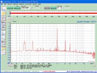
I replaced the 'good' transformer with an Edcor transformer and took a frequency response plot, and THD plots. Edcor has greater output.
When taking the THD plots I adjusted the input with the AudioTester to give the same 1KHz amplitude, and kept the volume control on the amp turned all the way up. Original transformer is second plot, Edcor third plot.
I guess next I'll replace the other transformer and see if that channel changes or not.
Attachments

I don't know what the 5U4G can actually take, but while most of these old power supply capacitors don't have a tolerance listed on them, the tolerances I've seen tend to be something like +80/-20%, so an extra 10uF on a capacitor that's supposed to be 40uF doesn't seem out of line with what the original 40uF cap might have actually been (40uF+80%=72uF). Then again, the original designer might have only been thinking about nominal values and not worst-case scenarios....
How critical is the input capacitance value? Spec for 5U4GB is 40uF. Can I get by with the 50uF section? Or do I need to drop back to the 30uF with an additional 10uF cap to get 40uF?
I can dispense with the 60uF for the tuner since there is no tuner.
Wired the second Edcor transformer up and had to tweak one of the input gain stages to match the outputs at 6Vrms. Then I cranked it up and measured the max output and one channel gives 8.3Vrms and the other 7.2Vrms. Looks like I'm driving the grid positive early on one channel.
I tried swapping tubes between channels with no effect. I finally dug out the tube tester and some tubes are weak. I matched up four out of the eight tubes I have and the results was pretty much the same.
I wired the original transformers back in and got 7.2Vrms on one channel and 3.2Vrms on the other. Looks like a bad transformer so I can either install the Edcors, or scrap it.
I now know why the original design had a balance control, 10% resistors result in really bad channel gain matching.
I swapped the original transformer primaries with the feedback disconnected and the problem switched channels. I pulled the transformers and the one that had low output was warm compared to the normal one.
I pulled both and will install the Edcor transformers.
I also bought metal film 2% replacements for every resistor in the amp. I might as well rebuild it completely.
I pulled both and will install the Edcor transformers.
I also bought metal film 2% replacements for every resistor in the amp. I might as well rebuild it completely.
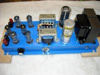
Project Phoenix
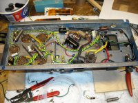
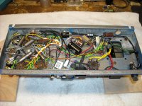
I stripped it down and started rebuilding it. TRWs are Polyester and need to be replaced but I'll have to order something to replace them with.
First photo when I first got it running. Second is progress to date. New Filter caps, additional RC stage in B+ filter, twisted heater wiring with NTC resistors and start of adding coupling caps.
I thought about replacing the sockets, but the holes are too large for the replacement ones I have. Then again if I replaced the sockets I'd probably switch output tubes as well.
At least the tubes are reasonably cheap.
Attachments

Finished wiring it tonight.
275V k-a at 32.6mA=8.98W total dissipation per tube, so the plates are running way below max. I may try cranking it up a tad by changing some ps resistors after I run it a while and take some readings.
I've got GNFB but no UL running right now. I may experiment with some Schade if I can figure it out for a PP amp without ITs.
Right now I've got Stevie Ray Vaughan cranking with 'Couldn't Stand the Weather'.
Sounds really nice, better than I expected with the budget Edcore's.
Attachments
I found a major screw up in the original schematic. They have a 470pf cap across the 180K anode resistor. I was wondering why it was there so I looked at the frequency response. Roll off starts below 10KHz and is really pathetic so I took them out.
At 10KHz the 470pF cap only represents 33.86K ohm. I wonder if they were there for a deficiency in the original transformers?
Speaking of the original transformers, I tacked them back in one at a time to once again test them. One is bad for sure. So the Edcor transformers stay in.
With 6dB of gnfb, the lower -3db point is down at 20Hz, and the upper -3dB point is way beyond 22KHz where it begins to sweep up.
I have to go back and measure it with my sine generator and scope as I haven't been able to get beyond 22KHz with AudioTester.
I'm still flogging a dead horse.
I ran the power up to 8W today and got a lower -3dB point of 20Hz (although obviously distorted on the scope). Upper -3dB point was beyond the 90KHz limit of the IG-18 I'm using.
I thought these were cheap transformers!
As an experiment I replaced the single cathode resistor (135 Ohm with 20uF in parallel) in the output with two 270 ohm resistors (each with their own 220uF bypass cap). I expected to see distortion go up, and instead it went down.
Then I replaced the two 270 ohm resistors with four 560 ohm resistors and again the distortion went down.
Finally I used clip leads to short the cathode resistors in pairs and finally in quad. Distortion went back up in each case.
The variable amount of capacitance may have impacted the test, however it seems to run counter to what I had read.
All four cathodes tied together with a common resistor and bypass cap should average the voltage since it is summing push pull currents from two channels. This should effectively approached a voltage source on the cathodes which should have produced a more stable operating point and less distortion.
But it didn't.
Why not?
It sounds better in the individual cathode resistor/capacitor configuration as well.
I matched four tubes out of a set of four I got at the ham fest with the four in the amp when I got it. Not a great match, but better than the original set by itself. I have more tubes on the way and will try to get a better match out of all of them.
Last edited:
The "Tree Streets" so named after trees are part of the old town and a historical district. As such they are limited to yard sales once a year, and most houses have a sale on that day. I don't get the paper so I wasn't aware it was today until I drove by around 2pm and saw a sign. I called the wife and said "lets go".
I missed a Sears Console Stereo for $40, but found this for $30.
Webcor 801068-16. Probably 8WPC. 12BA5s in pp with rather small opts. Active tone controls on a separate PCB.
Nice that the all important schematic is included. Interesting of note is the separate feedback winding in the OPTs.
Too bad it does not have an FM stereo tuner in it.
It will need new caps before powering it up, but it looks like it has been kept high and dry although quite dusty inside.
Just wanted to say Gimp- even putting in designer caps on a re-cap job on that old console will do wonders as you know. Did one last winter with all new Nichicon and Elna audios and I could believe my ears. Even using simple Dayton's for the polyesters was well worth it. Pretty fun.
I went with all new metal film resistors, Polyester caps for the input gain stage to phase splitter and KY40s from the phase splitter to the output tube grids.
I've got 4 new tubes from the ham fest, 9 from Ebay, and 5 more on their way from ebay. I hope to get at least four complete matched sets of two so that there will be enough for two complete sets of tubes.
It is currently biased at over 9W plate dissipation per tube so I may either increase the cathode resistors or the resistor in series with the screen tap to reduce dissipation below 9W per tube.
Final tweaking will be matching the tubes in sets, as I think everything is as good as it is going to get sound wise.
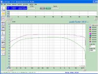
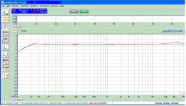
I just finished measuring frequency response is really impressive for the Edcor transformers specs of 40Hz-18KHz.
Time to take it up stairs and hook it up to the Heresy speakers.
I've got 6dB of gnfb and get this frequency response:
I've got 4 new tubes from the ham fest, 9 from Ebay, and 5 more on their way from ebay. I hope to get at least four complete matched sets of two so that there will be enough for two complete sets of tubes.
It is currently biased at over 9W plate dissipation per tube so I may either increase the cathode resistors or the resistor in series with the screen tap to reduce dissipation below 9W per tube.
Final tweaking will be matching the tubes in sets, as I think everything is as good as it is going to get sound wise.
I just finished measuring frequency response is really impressive for the Edcor transformers specs of 40Hz-18KHz.
Time to take it up stairs and hook it up to the Heresy speakers.
I've got 6dB of gnfb and get this frequency response:
Attachments
- Status
- Not open for further replies.
- Home
- Amplifiers
- Tubes / Valves
- Today was the anual Tree Street Yard Sale event