There's always this method as described in my wiki entry.
What he -^ said.
The condensed version: why muck about with toner transfer and scrubbing off the paper. Laser print onto a transparency and use pcb material pre-coated with photo resist. I use a small piece of glass to keep the transparency flat on the pcb and expose for 10 minutes under a "daylight" fluorescent lamp and then dunk in the developer. Can't go wrong.
If that sounds like a good method then read 5th element's description, which is wonderfully detailed but makes the whole process sound more complicated than it really is. (no offense intended.)
The resist method has never really appealed to me for some reason. If you want boards with resist pre-applied then that limits your choice of places to buy. I know you can apply the resist to bare PCB, but I've read that it doesn't always work too well that way. Plus the developer is just another chemical you have to keep around and deal with.
I guess I'm biased toward toner transfer since I spent so long perfecting my method. I couldn't imagine switching to the resist method at this point though.
I guess I'm biased toward toner transfer since I spent so long perfecting my method. I couldn't imagine switching to the resist method at this point though.
Hi everyone, I have a PCB circuit that has been done in eagle, the board is in a positive design and I can only get my hands in Negative photo resist, is there an easy way of reversing the positive design into a negative, I am not very familar with eagle and I cant even get it to print out the design in PDF I find the whole program very intense too put it midly, hope someone can help The file is the VSPS phono prestage, I have ordered the kit but I want to try it out and get some experience doing boards myself also.
Regards Jezza
Regards Jezza
Glossy magazine paper with a high clay content is better than all the photopapers. I got pit-free perfect boards using this method that matched any commercial board (my fr-4 is iron proof - can NOT lift a trace with heat alone).
For large traces or planes "press and peel blue" is the best. It leaves another layer of etch resist on top of the melted toner.
Using muriatic (HCL) and peroxide is NOT a chemical issue , you can neutralize it with lime or roadside gravel (CaC03-limestone).I am etching a dozen amps at a time with this method.
With glossy pages and my fr-4 , I can do 4 complete amps for under $10 (voltage boards and power boards) , all tinned with copperbased leadfree solder. This will take me about an hour + , even counting the drilling (below).
There is NO reason why professional boards cannot be made for next to nothing , with nothing (waste magazines).
BTW , dummy me just uses a paint program for the artwork (pix3).
OS
Attachments


Last edited:
I've found the toner method to be really tricky to get right, but I haven't tried the magazine paper yet. (Just regular copy paper, and the "premium photo paper" from Staples.)
With photoresist, once you've found a reasonable exposure time, it just works. The best way to figure out exposure time is to do a test strip. Take a scrap strip of board, draw a series of parallel lines on it and label them 5, 10, 15, 20, 25 with indelible marker. Place your artwork over the board, then the glass sheet. Cover all but the 25 section with something opaque. Expose for 5 minutes, then move the cover to reveal the next section. Repeat until 25 minutes have elapsed. Develop. See which time gave the best results. This is most valuable if the artwork isn't perfectly opaque. A sensible person might lay out a piece of artwork with the lines and numbers on it
For exposure, I initially used a photoflood lamp, the kind used for 8 mm home movies. Then, incandescent sun tanning lamps. Either of those occasionally show up at yard sales and thrift stores for cheap. Finally, I invested in a pair of 18" UV fluorescent tubes. F15T8/375BL was the GTE/Sylvania part number.
For one-off boards with through-hole components, applying the resist manually is a reasonable option, and uses the minimum in special materials and equipment. The secret is to tape 1:1 artwork to the board and drill the holes first. (If you don't have carbide drill bits, better to center punch the holes first because twist drills will wander.) Then, play connect-the-dots (in no particular order):
a) rubdown transfers (Radio Shack used to sell those). Those include DIP patterns, so ICs are feasible.
b) resist pen, or paint. Not pretty, usually.
c) cover the copper with plastic packaging tape, connect the dots in pen, then cut paths in the tape with a hobby knife. This is ideal for a ground plane, using other techniques for the solder side. It leaves plenty of copper on the board, minimizing etching time.
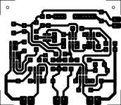
I was curious to see what the limit is with my toner transfer method so I did a little test. It seems 5mil line width with 5mil spacing is maybe just past the acceptable limit. I could probably make it come out better a second time using FeCL3 instead of HCI+H2O2. I left it in the etch a little too long and it was 2oz copper which isn't the best to use for thin traces due to etch-under.
1"x1".
1"x1".
Attachments

Last edited:
Hi,
the first bad line pair, West by North of the origin @ line 21/22, almost touches.
What is the line width and line gap at that location?
the first bad line pair, West by North of the origin @ line 21/22, almost touches.
What is the line width and line gap at that location?
Hi,
the first bad line pair, West by North of the origin @ line 21/22, almost touches.
What is the line width and line gap at that location?
Between cheap calipers, shaky hands, and the fact it's so darn small; it's a little difficult to measure accurately.
Width = >6mil
Gap = ~2mil
Most of the lines are severely over etched. The copper doesn't etch evenly so by the time one area is at the perfect etch point, other areas are either not etched enough or already etched into oblivion.
I have no need for 5mil line width though. 15mil is about the smallest I ever use.
I've read it suggested that if you do make your own boards and have to drill your own holes, and you do it quite often, it might be wise to invest in a small drill press.
I've read it suggested that if you do make your own boards and have to drill your own holes, and you do it quite often, it might be wise to invest in a small drill press.
I use a dremel drill press with a lithium-ion cordless dremel. Mine is actually a Craftsman model #53169, but it's identical to the dremel version.
- Status
- Not open for further replies.
- Home
- Design & Build
- Construction Tips
- To etch or not to etch-that is the question?