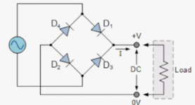
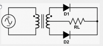
I've been reading (searching the net) on the differences between the two:
For an end user, I feel the transformer construction advantage might be not as useful.
In my case, I'm looking at two transformers which cost the same.
Are there any other electrical advantages/disadvantages of one or the other? Is the current output the same/similar?
PS: I need +/- 30+ VDC after the rectifiers.
Thank you.


- It seems a bridge rectifier is more efficient in terms of the transformer construction.
- The bridge rectifier has a bigger voltage drop because of the two diodes (maximum of .7 each)
- Ripple is higher on a bridge rectifier
For an end user, I feel the transformer construction advantage might be not as useful.
In my case, I'm looking at two transformers which cost the same.
- 300VA 2 x 12VAC @ 12.5A (will be used in full-wave mode with ground center-tap. connecting the 2 secodaries in series to get 24VAC)
- 300VA 2 x 24VAC @ 6.25A (will be used in a bridge rectifier configuration)
Are there any other electrical advantages/disadvantages of one or the other? Is the current output the same/similar?
PS: I need +/- 30+ VDC after the rectifiers.
Thank you.


Last edited:
Apart from eventual differences in xformer cost, I don't see any advantages or disadvantages except from the extra diode drop.
Ripple should be the same in both cases.
Jan
Ripple should be the same in both cases.
Jan
in my example above (I gave actual transformer "specs"), what's the difference (excluding voltage drop) on the voltage/current immediately after the rectifiers?Depends what voltage/current you are expecting.
Thanks
This may help you understand what goes on and some theory behind it;
https://www.elprocus.com/bridge-rectifier-circuit-theory-with-working-operation/
Plenty of explanations out there, just look for them.
https://www.elprocus.com/bridge-rectifier-circuit-theory-with-working-operation/
Plenty of explanations out there, just look for them.
I'm a little confused with your xformer specs. You said:
Both configurations are full wave.
Or you use only one secondary 24V as input to the full bridge but that wasts half the xfrmr capacity.
Possibly I misunderstand, but a drawing would help.
Jan
- 300VA 2 x 12VAC @ 12.5A (will be used in full-wave mode with ground center-tap. Connecting the 2 secodaries in series to get 24VAC)
Both configurations are full wave.
- 300VA 2 x 24VAC @ 6.25A (will be used in a bridge rectifier configuration)
Or you use only one secondary 24V as input to the full bridge but that wasts half the xfrmr capacity.
Possibly I misunderstand, but a drawing would help.
Jan
I had the impression that I can get +/- ~30 VDC from 2x12VAC (connected in series into a fullwave + center-tap ground configuration)I'm a little confused with your xformer specs. You said:
I had the impression that I can get +/- ~30 VDC from 2x12VAC (connected in series into a fullwave + center-tap ground configuration)
Do you want a unipolar supply with +30VDC / 0VDC
or a bipolar supply with +30VDC / 0VDC / -30VDC ?
Last edited:
I believe that a tapped xfmr should cost more because of production complexity.Are there any other electrical advantages/disadvantages of one or the other? Is the current output the same/similar?
On the other hand, a single secondary winding is as simple as possible. A bridge rectifier can be purchased as a single unit and bolted to the chassis. The parts list will be shorter.
bipolarDo you want a unipolar supply with +30VDC / 0VDC
or a bipolar supply with +30VDC / 0VDC / -30VDC ?
I was looking at a few transformers from mouser/digikey and etc and there's no difference to costs in the same power output. (example: hammond 300VA toroidal all costs the same in mouser)I believe that a tapped xfmr should cost more because of production complexity.
go with bridge rectifier even at the cost of extra diode drop , the transformer utilisation factor gets improved, lesser transformer losses.
For a single center tapped tranny, use single bridge rectifier.
For 2 isolated trannys in series , you have an option to use Dual bridge rectifier
I'm planning to use 2 salvaged UPS trannys with 2 bridge rectifiers
For a single center tapped tranny, use single bridge rectifier.
For 2 isolated trannys in series , you have an option to use Dual bridge rectifier
I'm planning to use 2 salvaged UPS trannys with 2 bridge rectifiers
Last edited:
You won't get +30/0/-30 from 2X12VAC. You can get +30/0 , or -30/0 , or +12/0/-12 from 2X12VAC.bipolar
Jan
Its 12 VAC x 1.41 = 17VDC at no load using capacitor as filter
so about +/-17VDC for 2 trannys
But keeping tolerances in mind, a 12VAC tranny is around 13 to 13.5 VAC at no load, can drop 1 to 2 V at full load depending upon its winding resistance
so about +/-17VDC for 2 trannys
But keeping tolerances in mind, a 12VAC tranny is around 13 to 13.5 VAC at no load, can drop 1 to 2 V at full load depending upon its winding resistance
You need a 2 x 22V transformer for that if it is for unregulated voltages to a power amplifier. This is called a bipolar PSU. Current rating of the transformer depends on the load. Schottky diodes in single bridge configuration and CLC filtering are advised.I need +/- 30+ VDC after the rectifiers.
If you want regulated +/- 30V DC things will be different.
You did not even mention what the purpose is for this PSU but it would help to be specific. This avoids clutter and off topic stuff.
Last edited:
Ignorance is easily corrected. Stupidity not so. You don't show any of the latter, on the contrary. 😎thanks everyone for the patience. My ignorance showed there 😀
But you still did not answer the questions. Questions that are asked to help you solve your issues.
rayma said:
Do you want a unipolar supply with +30VDC / 0VDC
or a bipolar supply with +30VDC / 0VDC / -30VDC ?
mjayviper said:
bipolar
But BOTH your examples show UNI-polar supply ... wtf? 🙂


this is logically impossible, it´s either "+/-" or "+" , pick one.: I need +/- 30+ VDC after the rectifiers.
but the question itself is wrong/illogical.But you still did not answer the questions. Questions that are asked to help you solve your issues.
As posted, it does not have an answer.
This can give you +/-16V (DC is implicit by the use of + or -signs)I had the impression that I can get +/- ~30 VDC from 2x12VAC (connected in series into a fullwave + center-tap ground configuration)
You mean respectively "+30/0 , or -30/0 , or +15/0/-15" I think?You won't get +30/0/-30 from 2X12VAC. You can get +30/0 , or -30/0 , or +12/0/-12 from 2X12VAC.
Last edited:
anything can be built to spec, traffos and psu included...
i favor the 2 diode full wave voltage doublers, why?
1. lower voltage, makes traffo design and build much easier
2. simple to design and construct..
3. ripple voltage is also 120hz on 60hz line
ripple voltage is directly proportional to load current and inversely proportional to capacitance and can be designed to requirements....
Patrick Turner, RIP, advocated the use of this topology...
- Home
- Amplifiers
- Power Supplies
- to an end user/builder, does it matter if the rectifier section is full wave (2 diodes) vs bridge rectifier (4 diodes)?