I have been running my Ladegaard for about a year now and although it works well I am convinced things could be better than they are.
(you can see my current version here: one and two ).
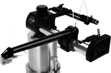
Last night I tried to find out where improvements could be found and I think I have at least identified one problem. It turns out that the aircushion between base and slider is not at all uniform from top to bottom. The results is that the bottom of slider is able to move backward and forward quite a bit (see pic below).
I want to ask other users to check their arms to see if they have this problem as well.
I have been thinking about a possible solution and I can see two options that might work:
1. Drill the holes in the base in two rows instead of one (the second row will have to be a lot further down)
2. Drill the holes in one row but much further down.
I think option nr. 1 has the biggest chance to work
Reactions Please!
(you can see my current version here: one and two ).
Last night I tried to find out where improvements could be found and I think I have at least identified one problem. It turns out that the aircushion between base and slider is not at all uniform from top to bottom. The results is that the bottom of slider is able to move backward and forward quite a bit (see pic below).
I want to ask other users to check their arms to see if they have this problem as well.
I have been thinking about a possible solution and I can see two options that might work:
1. Drill the holes in the base in two rows instead of one (the second row will have to be a lot further down)
2. Drill the holes in one row but much further down.
I think option nr. 1 has the biggest chance to work
Reactions Please!
Attachments

My only observation that relates to this is that you are better off if you can have a higher pressure and a heavier slider - you will get a "harder" air cushion and the result is a better sound. My experience is that I have been using aquarium pumps with a marginal pressure and this is less than ideal - a compressor or a compressed air source like a pressure tank would be better. Then you can pile on a litttle more weight and the sound tightens up a little.
Nice looking implementation - I like your arm lift!
-j
Nice looking implementation - I like your arm lift!
-j
Peter,
I would stick with the existing holes arrangement around centerline. It seems to me, the slider is more stable both statically and dynamically this way. The static air pressure under the slider within the area below the holes is maximum and equal, assuming the air flow at the slider ends is negligible. Above the holes, the pressure starts to drop towards (air is flowing from high to low pressure area). So, if you place two rows of holes, the air will tend to flow through the upper row (lower backpressure), thus increasing the total air flow and associated hiss and induced vibrations also. Placing the holes in the bottom part only may lead to dynamic instability, when the slider starts to rock due to variable stylus friction forces on loud passages.
As for making the Ladegaard better, methinks it shall be treated essentially like the Schreder arm, namely addressing the stylus induced vibrations by the armwand and counterweight proper damping, because both arms are decoupled from the armboard (no rigid mechanical bearing here). The most noticeable improvement I got was due to double damped armwand and more rigid hedshell and arm-to-slider connection.
Cheers,
Michael
peterr,
why not feed the air to the slider instead to the rail?
symmetric load, 100% nozzle coverage would be the benefit.
why not feed the air to the slider instead to the rail?
symmetric load, 100% nozzle coverage would be the benefit.
I've always wondered how to minimize the stiffness of the air tube to acceptable levels when supplying the air to the slider. I've seen applications (including the Kuzma linear arm), so I guess it can be made to work, but I would think you could never make it as flexible as the wires.
A possible way of making the bearing more rigid would be to change the slider to be four sided (a square tube) and put another, inverted 'base' above it (creating two opposed air bearings). This might require a change to the vertical bearing. The lower bearing would need to be supplied higher pressure to the degree required to lift the arm. The advantage would be that you could increase the pressure(s) to create a more rigid bearing while not increasing the air gap or having to increase the weight (beyond the increase caused by the square tube slider, of course). In effect, the upper bearing would load the lower.
This idea occurred to me several years ago, but I never implemented it. I ended up building an arm similar to the ET2 instead. But, I still think it's worth consideration.
Paul Ebert
flexible tubing
Bernhard,
Could you please point out any source for affordable superflexible tubes?
Thanks,
Michael
Bernhard,
Could you please point out any source for affordable superflexible tubes?
Thanks,
Michael
Konnichiwa,
I have always wondered about a "maglev" version. We know maglev is unstable, but that is what we want.
Put neodymium magnets into the sled and use electromagnets to get the sled to float, or just more ND Magnets.
Together with the Laadegard style aluminum angle you get eddy current damping for free so the lateral movement will be frictionless for slow movement but heavily damped for fast movement.
The V-Shape of the magnetic field will stabilise the system in the forward/backwards direction and the left/right movement will be in effect completely free, but damped by the eddy current damping.
Now, the question is can this be made to work?
Sayonara
peterr said:I have been running my Ladegaard for about a year now and although it works well I am convinced things could be better than they are.
I have always wondered about a "maglev" version. We know maglev is unstable, but that is what we want.
Put neodymium magnets into the sled and use electromagnets to get the sled to float, or just more ND Magnets.
Together with the Laadegard style aluminum angle you get eddy current damping for free so the lateral movement will be frictionless for slow movement but heavily damped for fast movement.
The V-Shape of the magnetic field will stabilise the system in the forward/backwards direction and the left/right movement will be in effect completely free, but damped by the eddy current damping.
Now, the question is can this be made to work?
Sayonara
Re: flexible tubing
Michael,
from my calculations, there is not much air-flow needed. So i settled on a cheap silicone insulation tubing of lowest available diameter, say 1mm. I made an experiment: my comperessor could not make this tubing blow at 8 bar. I used the Coroplast brand.
Good quality, costs a joke.
You may look puzzled howsuch a weak thing as silicone insulation tubing can stadn 8 bar, but the pressure limit of a container is proportional to 1/r^3 . So, the thin tubing, having a very low r, has a high pressure limit.
How to get a terminal piece to the tubing:
take a piece of plexiglas/perspex, drill a hole with the tubing's outer dia into the perspex plate's small side, glue the tubing into the hole with cyanacrylate. Then drill another, bigger hole thru the perspex's big side, crossing (=drilling out) the tubing. Now the tubing's end should be flush with the bigger hole's surface. You can use this perspex piece to connect it via a hollow screw to the air supply.
I would expect 3 out of 4 tries to be successful if you are not extraordinarily clumsy 🙂 and if you are practising a bit, you may have a 98% yield.
Having abandoned my Ladegaard project (currently designing an active linear tracker with zero lateral stylus forces) i have more tubing than i ever may need. Send me your adress via email, i send you a big sample.
Michael,
livemusic said:Bernhard,
Could you please point out any source for affordable superflexible tubes?
from my calculations, there is not much air-flow needed. So i settled on a cheap silicone insulation tubing of lowest available diameter, say 1mm. I made an experiment: my comperessor could not make this tubing blow at 8 bar. I used the Coroplast brand.
Good quality, costs a joke.
You may look puzzled howsuch a weak thing as silicone insulation tubing can stadn 8 bar, but the pressure limit of a container is proportional to 1/r^3 . So, the thin tubing, having a very low r, has a high pressure limit.
How to get a terminal piece to the tubing:
take a piece of plexiglas/perspex, drill a hole with the tubing's outer dia into the perspex plate's small side, glue the tubing into the hole with cyanacrylate. Then drill another, bigger hole thru the perspex's big side, crossing (=drilling out) the tubing. Now the tubing's end should be flush with the bigger hole's surface. You can use this perspex piece to connect it via a hollow screw to the air supply.
I would expect 3 out of 4 tries to be successful if you are not extraordinarily clumsy 🙂 and if you are practising a bit, you may have a 98% yield.
Having abandoned my Ladegaard project (currently designing an active linear tracker with zero lateral stylus forces) i have more tubing than i ever may need. Send me your adress via email, i send you a big sample.
Maglev Ladegaard
Actually, - I have been pondering with the same idea for a maglev version of Ladegaard....but using ND mag's and mild steel for the lower V part.....
In theory, -it should work, but I haven't done any tests or calcs to see how much weight it will support for the sled and arm....
Wonder if the stray field would influence the PU, though....????
Re: Maglev Ladegaard
Konnichiwa,
It might, but remember fieldstrength falls to the square of distance and the field is in essence static and directed not in line with the Pickups own magnets. So whatever happens there is low in magnitude and static or extremely low frequency.
Sayonara
Konnichiwa,
AuroraB said:Wonder if the stray field would influence the PU, though....????
It might, but remember fieldstrength falls to the square of distance and the field is in essence static and directed not in line with the Pickups own magnets. So whatever happens there is low in magnitude and static or extremely low frequency.
Sayonara
make it shorter
I belive the "air supplied to the slider" design has an important advantage for Ladegaard arm: you may substantially rise the air pressure, or in other words, bearing stiffness, by simply shortening the slider. If you make it, say 90 mm instead of current 180, you shall double the pressure, to keep the same lift force (equivalent to the weight) and air gap. (I would stay with the current angle width, for not to affect rotational stability). In the same time you may reduce the total air flow, because there are no open holes, which are just bleeding most of the pressured air and producing disturbing hiss. It means you may stay with existing pump.
Worth trying, IMHO, providing Bernhard will be so kind and supply me with his silicone tube (I hope you get my mail?).
Stay tuned for test report.
Re: make it shorter
my email adress was outdated .... please try againlivemusic said:..., providing Bernhard will be so kind and supply me with his silicone tube (I hope you get my mail?).
Stay tuned for test report.
maglev sled prototype
i've just got 90 pieces of 9.525mm x 9.525mm x 3.175mm 48N ND magnets to try this out. the angle bar that i got is roughly 0.5mm thickness to ensure that the sled is as light as i can get it to be (in case the ND magnets cannot float the required weight of arm and counterweight)
will try to prototype something out of this and report on the feasibility of the maglev sled.
btw, what weight would the sled be required to float? or, what should the approximate weight of the arm and counterweight be?
Kuei Yang Wang said:
Put neodymium magnets into the sled and use electromagnets to get the sled to float, or just more ND Magnets.
Together with the Laadegard style aluminum angle you get eddy current damping for free so the lateral movement will be frictionless for slow movement but heavily damped for fast movement.
The V-Shape of the magnetic field will stabilise the system in the forward/backwards direction and the left/right movement will be in effect completely free, but damped by the eddy current damping.
Now, the question is can this be made to work?
i've just got 90 pieces of 9.525mm x 9.525mm x 3.175mm 48N ND magnets to try this out. the angle bar that i got is roughly 0.5mm thickness to ensure that the sled is as light as i can get it to be (in case the ND magnets cannot float the required weight of arm and counterweight)
will try to prototype something out of this and report on the feasibility of the maglev sled.
btw, what weight would the sled be required to float? or, what should the approximate weight of the arm and counterweight be?
Re: maglev sled prototype
Konnichiwa,
Actually, you want different intertia vertical and horizontal. At any extent, the floated weight would be no more than 250 - 500g, can be made less but eventually the inertia in the horizontal axis becomes too low.
One thing though, with this and the air floating arm perfect leveling of table and arm are essential!
Sayonara
Konnichiwa,
garbage said:btw, what weight would the sled be required to float? or, what should the approximate weight of the arm and counterweight be?
Actually, you want different intertia vertical and horizontal. At any extent, the floated weight would be no more than 250 - 500g, can be made less but eventually the inertia in the horizontal axis becomes too low.
One thing though, with this and the air floating arm perfect leveling of table and arm are essential!
Sayonara
unsuccessful attempt
was trying to see if the floating mechanism works this afternoon...
tried to put the magnets on the lower sled and used a small piece of angle bar for the upper sled with nd magnets on the bottom.
turned out that the particular magnets that i got attracts at the sides for both poles. thus, when i manually try to float the upper sled, it will be attracted to the sides of the magnets on the lower sled, causing both sled to be stuck together.
what might work is a larger piece of nd magnet for the lower sled and an upper sled that will float within the limits of the size of the lower sled nd, with weight taken into account.
don't think i'll further investigate this as ordering nd magnets from ebay us to singapore is not exactly cheap...
was trying to see if the floating mechanism works this afternoon...
tried to put the magnets on the lower sled and used a small piece of angle bar for the upper sled with nd magnets on the bottom.
turned out that the particular magnets that i got attracts at the sides for both poles. thus, when i manually try to float the upper sled, it will be attracted to the sides of the magnets on the lower sled, causing both sled to be stuck together.
what might work is a larger piece of nd magnet for the lower sled and an upper sled that will float within the limits of the size of the lower sled nd, with weight taken into account.
An externally hosted image should be here but it was not working when we last tested it.
don't think i'll further investigate this as ordering nd magnets from ebay us to singapore is not exactly cheap...
Silly comment--or maybe not ??
All magnets must have the same polarity facing upwards, and the sled magnets same polarity facing downwards...
I was wondering of clamping the lower magnets between two angle bars of mild steel, to make the field more evenly distributed....but I don't have suitable magnets at the moment...
Just my 2 c's................
Re: Silly comment--or maybe not ??
i took some pains to align the magnets with uniform polarity... i test for polarity before sticking them to the angle bar.
the small nd magnets are a little difficult to separate once the are stuck to each other.
AuroraB said:All magnets must have the same polarity facing upwards, and the sled magnets same polarity facing downwards...
i took some pains to align the magnets with uniform polarity... i test for polarity before sticking them to the angle bar.
the small nd magnets are a little difficult to separate once the are stuck to each other.
Airgap width
In my quest to try and improve upon my Ladegaard I want to try and make a more traditional air bearing, one that is not just pressurized from below but all around and with the air fed to the slider (something like the Kuzma ).
I know very little about pneumatics but I need to find out what the airgap should have to be in a design like that. I have Googled around but haven’t found what I was looking for. Are there any simple rules to follow? All knowledge is appreciated.
Attachments
peterr said:Airgap width
In my quest to try and improve upon my Ladegaard I want to try and make a more traditional air bearing, one that is not just pressurized from below but all around and with the air fed to the slider (something like the Kuzma ).
You might want to check out the bearings sold by new way:
http://www.newwayairbearings.com/
I used one of their 1/2" bushings for my arm. It should work with most 'precision ground' shafts. I bought mine from McMaster-Carr. I would not be surprised if the Kuzma uses one of these.
One benefit of these is that they are almost completely silent. No air hissing. The drawback is that they require high pressure - 20 psi at least. I used 30. I was not able to find a quiet pump that provided that much pressure. I ended up using a relatively quiet air compressor. But it made a loud noise when it reached pressure and switched the pump off, which happened about every other minute. Even in my basement, it was a noise problem.
Paul Ebert
Paul,
Thank you for the link. A lot of info there.
It does indeed look like Kuzma uses these bearings.
I might very well end up buying one of these but before I do I want to try and find a way to do it in the best Ladegaard tradition on the kitchentable using simple DIY materials.
Thank you for the link. A lot of info there.
It does indeed look like Kuzma uses these bearings.
Does this mean you no longer use your airbearing arm?it was a noise problem.
I might very well end up buying one of these but before I do I want to try and find a way to do it in the best Ladegaard tradition on the kitchentable using simple DIY materials.
- Status
- Not open for further replies.
- Home
- Source & Line
- Analogue Source
- To all Ladegaard builders