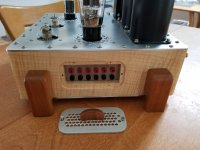
Didn´t read the whole thread but if you have to drillb 100 heatsinks or more (as in commercial amp building) you can have a mild steel plate with hardened (cemented/nitrurated) inserts to guide the drill bits with perfect repeatability.I realize this is very old. Just wondering where this went if anywhere. I would definitely
be interested in a drilling jig made of steel or steel inserts for drilling. Anybody know more. Using an old TO-3 would just give you the outer mounting holes but not the pin holes.
I have one made to drill speaker magnet plates and cast or stamped speaker frames so they always match perfectly.
For just a few, just mark them properly and punch guide holes, and work slowly, until drill bit bites well, if it slips or wobbles it will be a mess. (don´t ask
Keep heat sink always oriented same way when drilling; if holes have a small displacement error (it happens), at least all will shift same way so no big deal.
Like an old friend said: "problems which can be solved with money aren´t really problems"Yeah that doesnt sound bad. It would still be nice to have a drill jig that you guide your bit with.
I use the amplifier pcb as a template for the holes.
Especially useful for multiple packages.
I found the trick for not enlarging the holes is to use a battery hand drill placed in the hole before starting it up.
Doesn't really matter if holes get slightly enlarged as next time you use the next pcb.
On my dual TO3 amp:
Place pcb over heatsink as centrally as possible.
Use punch to make first hole near end of heatsink.
Drill hole to 3.5mm and put a bolt through pcb and heatsink.
Line up heat sink and pcb again and punch through opposite end of heat sink.
Drill 3.5mm hole and put bolt through it.
Tighten up both bolts.
Now using hand drill put drill through rets of holes and start up drill to make hole.
Remove pcb from heat sink and drill out all holes to required size.
Deburr all holes.
Done !
Last edited:
The original question was not how to mark hole position but how to *guide* the drill, not the same at all.

this one is made for accurate repeatable drilling of wood, same principle applies.
Red is cheap mild steel, chromed is very hard steel insert, some have a hard chrome coating (not decorative chrome as applied to car or motorcycle parts).

The commercial wood drilling guide costs 45 GBP so a custom TO3 one will certainly cost >100 GBP
Too much for a home builder, nothing for a Factory.
Drill Bushes
Slender and cantilever type cutting tools, mainly drills, usually suffer from run – out due to possible errors in the drill, sockets and drilling machine spindle and finally in the overall alignment. Such run out causes over sizing, out of roundness and surface roughening of the drilled holes. Such run out aggravates further with the increase in drill speed (rpm) and the thrust force, especially if the drill is not geometrically symmetrical. This often leads to, in addition to poor product quality, breakage of the drill by bending and / or buckling. To reduce such problems, bushes are used in the jigs to guide the drill bits as indicated in Fig - The bushes, used to guide and properly locate drills, reamers etc. are generally made of carbon or alloy steel and made wear resistive by hardening to RC 60 and above. Often bushes are also made from grey cast iron for antifriction and protection of the tools. - The hardened jig bushes are finished outside by grinding and inside by grinding and lapping if high precision is insisted. - The bush’s length should be sufficient (≥ twice drill diameter) and its diameter should be slightly larger than the drill diameter - Design and construction should enable easy and quick proper fitting and removal or replacement of the bushes - Bushes should not come out from its seat along with the drill during its return.

this one is made for accurate repeatable drilling of wood, same principle applies.
Red is cheap mild steel, chromed is very hard steel insert, some have a hard chrome coating (not decorative chrome as applied to car or motorcycle parts).

The commercial wood drilling guide costs 45 GBP so a custom TO3 one will certainly cost >100 GBP
Too much for a home builder, nothing for a Factory.
Take a dead TO-3. Preferably steel, not alloy. Punch the pin-seals out with hammer and small tool. Fit a drill to the seal hole and drill through the lid. Now you have a drill guide to get the holes in the right places. If the pin holes must be larger, go at the sink again with a bigger drill. If you have a steel TO-3 you can do dozens of holes before wear gets bad.
Last edited:
Levistubby made a valid point, and also described the exact process I use. Just draw your design to scale on paper (or use cheap CAD software and print it like I do), fix the drawing onto the workpiece with blue tape, then punch, drill and deburr. Done.Having a template for a single device is not always a great help. It depends on whether it can easily be clamped to the heat sink while it is being used. In a lot of cases it is easier to draw the layout for all the devices on paper, then lightly stick the paper to the heat sink, centre punch the position of all the holes through the paper, remove the paper and drill the holes.
The advantages are many:
- Your patterns, hole sizes and locations are only limited by your imagination.
- The tools involved are relatively simple and inexpensive (benchtop drill press, drill bits, prick/center punches, etc.)
- Said tools are versatile (i.e. useful for other projects).
Attachments
Reminds me of my second amp build in 1980 which was a Maplin 225WRMS "disco" amplifier. It had 2 pairs of 2N3055 and MJ2955.
I was a bit worried about the insulating washers so chickened out of using one heat sink and used one for the 2N3055's and the other for the MJ2955's.
This meant the holes weren't quite as critical as no insulators were needed in a wooden open backed box.
I was a bit worried about the insulating washers so chickened out of using one heat sink and used one for the 2N3055's and the other for the MJ2955's.
This meant the holes weren't quite as critical as no insulators were needed in a wooden open backed box.
Having a template for a single device is not always a great help. It depends on whether it can easily be clamped to the heat sink while it is being used. In a lot of cases it is easier to draw the layout for all the devices on paper, then lightly stick the paper to the heat sink, centre punch the position of all the holes through the paper, remove the paper and drill the holes.
Or make sure you have extra boards from a PCB run, and use one of them for the drilling template. Yeah, the holes will wear quickly, but you can do two, four, eight of them the same, with all 14 of the transistors properly aligned with respect to one another. After you’re done with that batch, you might not need that particular template anymore. If you do, you’’ll be reordering boards anyway.
- Status
- This old topic is closed. If you want to reopen this topic, contact a moderator using the "Report Post" button.
- Home
- Amplifiers
- Solid State
- TO-3 Drilling Jig

