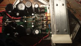
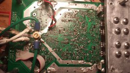
I have an old optimus car amp from the early 90's, designed and manufactured by Pyramid for Radio Shack, that uses BD907/8 pairs for 50 watts into 4 ohms. After a lot of abuse it is still in perfect condition electronically, not so much cosmetically.
BD907 pdf, BD907 description, BD907 datasheets, BD907 view ::: ALLDATASHEET :::
BD907 pdf, BD907 description, BD907 datasheets, BD907 view ::: ALLDATASHEET :::
BD911/912 seem to be the survivors of that series TO220 devices. I used them for the occasional cheap 30W/8 ohm build with its aluminium case as heatsink. I don't see why you couldn't achieve 50W/4 ohms with these using decent heatsinks and the right power supply but I haven't had the need - yet 😀.
I don't see why you couldn't achieve 50W/4 ohms with these
I know of a serial manufacture 200W monaural power amp that used 6 pairs of TO-218 devices (125W Pd) for the Mark I.
A TO-218 package has 2.5 times more thermal capacitance (copper) than a TO-220, thermal resistance from case to sink with a mica insulator is roughly 2.5 times lower.
Still means sufficient pairs of BD911/912 are good for a >100W power amp.
(I built Pass A75 monaural full Class A amps with 12 pairs of IRF630/9630 per channel. 74W Pd devices in TO-220 dress, cost peanuts in batches of a few hundred. MOSFET, not BJT, so not entirely comparable, but close to 200W idle dissipation and used to drive ESL63s)
The biggest destroyer of power transistors in class AB linear configuration is instantaneous power dissipation. Since speakers are not linear in their impedance, there is that small time period when large currents conduct at the same time there is more voltage across the output device due to phase shifting of speaker Z. A higher initial die temperature before the heat spike may cause the BJT to hot spot and fail. Due to the smaller surface area of the TO-220 tab, the thermal resistance of the mica (or whatever) insulator layer is higher than in the same material for TO-3P (247). I generally just use mica and grease. It is cheap, and works fine for me. Bipolars can be limited by the secondary breakdown and this can be a problem for driving 1 pair to the upper Pd limits.
Mosfets, particularly verticals are really only limited in Pd by the temperature at which the plastic melts, 175C or so, would be the point of destruction. That is pretty hot and I would not recommend running near that hot even for mosfets. De-rated Pd is significantly less at high die temperatures. Type of vertical fet is important, you can’t use 2nd and 3rd generation, Trench fets and Nexfets as outputs because they are different and tend to hot spot and fail like BJTs. Plural well mosfets and also I find that the singular well planer stripe types are particularly tough.
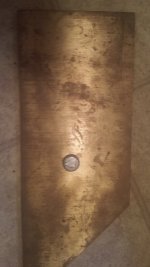
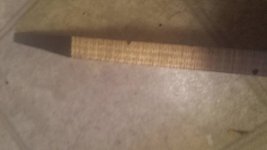
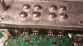
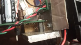
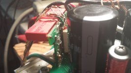
When looking at datasheets for a FQP47P06 and the FQA47P06, the only difference is the package size and the increased Pd figure related to that. They are the same transistor, same die. So it dawned on me one day that if one could effectively increase the package size of the TO-220 version, it then should be able to handle more power. Working with this theory, I mounted the transistors directly to a ‘thermal capacitor’, a piece of high copper brass. Scrap metal otherwise. 🙄 The density of the ‘thermal capacitor’ allows it to absorb high intensity thermal spikes from the die maintaining a rapid heat transfer into the brass piece. The rectangle shaped brass piece is mounted into the corner of ¼” aluminum bracket and separated with mica layer and grease on the front and bottom. Tightly mounted with 8-32 screws and nylon bushings on the bottom. Since the surface area of the mica layer is 5-6 times that of the TO-220 tab, the overall thermal resistance of the mica layer is greatly reduced. These mosfets do not care to operate at a higher average temperature as long as the peak temperature does not exceed the limits of the package. I did place both of my old (newly refurbished tho😀) Cerwin AT-10’s in parallel on one channel. It had no problem driving them with sine wave signal, even with my bench transformer (1.4KVA toroid🙂). The devices did get a little warm to the touch after a few minutes as heat sink temperature rose. Bottom line is, how fast you can remove the heat from the die in order to maintain reasonable die temperature.
Mosfets, particularly verticals are really only limited in Pd by the temperature at which the plastic melts, 175C or so, would be the point of destruction. That is pretty hot and I would not recommend running near that hot even for mosfets. De-rated Pd is significantly less at high die temperatures. Type of vertical fet is important, you can’t use 2nd and 3rd generation, Trench fets and Nexfets as outputs because they are different and tend to hot spot and fail like BJTs. Plural well mosfets and also I find that the singular well planer stripe types are particularly tough.
When looking at datasheets for a FQP47P06 and the FQA47P06, the only difference is the package size and the increased Pd figure related to that. They are the same transistor, same die. So it dawned on me one day that if one could effectively increase the package size of the TO-220 version, it then should be able to handle more power. Working with this theory, I mounted the transistors directly to a ‘thermal capacitor’, a piece of high copper brass. Scrap metal otherwise. 🙄 The density of the ‘thermal capacitor’ allows it to absorb high intensity thermal spikes from the die maintaining a rapid heat transfer into the brass piece. The rectangle shaped brass piece is mounted into the corner of ¼” aluminum bracket and separated with mica layer and grease on the front and bottom. Tightly mounted with 8-32 screws and nylon bushings on the bottom. Since the surface area of the mica layer is 5-6 times that of the TO-220 tab, the overall thermal resistance of the mica layer is greatly reduced. These mosfets do not care to operate at a higher average temperature as long as the peak temperature does not exceed the limits of the package. I did place both of my old (newly refurbished tho😀) Cerwin AT-10’s in parallel on one channel. It had no problem driving them with sine wave signal, even with my bench transformer (1.4KVA toroid🙂). The devices did get a little warm to the touch after a few minutes as heat sink temperature rose. Bottom line is, how fast you can remove the heat from the die in order to maintain reasonable die temperature.
Attachments
That's really all-out dedication to TO220.
If you really want all out dedication to TO-220 what you want to do is build an S-Leach type amp with 10 pairs of TIP41/42C. It would work and be cheap. Anyone want to try it?
I know of a serial manufacture 200W monaural power amp that used 6 pairs of TO-218 devices (125W Pd) for the Mark I.
I've got a car amp that does 2x200 /2R with 3 pair of TO-218 (TIP35/36) per channel. It seems to be enough.
Hi Guys
Tens of thousands of commercial product has been built with TO-220 output devices. There is no difference using this package or the larger ones inasmuch as with any device you intend to utilise, you have to respect the power limits.
If the FJP5200 is in fact the same die stuck in a smaller package, then it will only be good to the 80W claimed for the small package. if you take the TO-247 SOA and move the thermal limit line to the left so that its points fall where 80W dissipation would be, then you have a reasonable graph to work with. Even without doing that, you would have to aim at low power and stay within the 80W rating.
It's not rocket science.
Have fun
Sure, not rocket science but 'thing is, you can buy lots of TO220 parts very cheaply and locally, improve the cooling over standard recommended methods without getting prohibitively expensive and still afford to match devices. Many DIYs can then achieve what commercial manufacturers working off standard part spec. sheets can't. Some can do somewhat better - or at worst die tryin' 😉
That's really all-out dedication to TO220.
HA! yeah, well those particular TO-220 transistors literally cost about 1 dollar each.😀 Larger package costs more. Also, the circuit is more compact with TO-220 and driving only one pair is less complicated requiring no matching and such.
use the formula:I'm looking at making a (physically) smaller power amp using TO-220 output transistors, i.e. Fairchild's 2SC5200 family.
I'm not sure how to estimate power output at 8/4ohms because SOA curves don't exist on the datasheets for the smaller parts. It might be the same die in different packages ? as the TO-220 and TO-264 parts have the same capacitance and Fairchild just cut'n pasted the specs. Only difference is the thermal resistance is 2-3x higher for the small parts.
"Same transistor is also available in:"
Power Diss.; RθJC Junction to Case
TO-264 package, 2SC5200/FJL4315 : 150 watts : 0.83°C/W
TO-3P package, 2SC5242/FJA4313 : 130 watts : 0.96°C/W
TO-220 package, FJP5200 : 80 watts : 1.25°C/W
TO-220-F package, FJPF5200 : 50 watts : 2.50°C/W
Any guidance on calculating pwr output from a pair or two of the smaller guys is appreciated.
Maximum output power approximately equal to sum of device Pmax divided by "factor".
Factor = 4 for mosFETs, or = 5 to 6 for BJTs. Use 6 for poor SOA devices like 2sa1943/c5200.
i.e. 4pair of 50W MJE15034/5 gives a total Pmax of 8*50 = 400W and results in a maximum output of ~ 80W per channel.
4pair of IRF540 results in ~ 300W per channel. That's why they use them to drive 2ohms speakers in cars/automobiles.
It's not rocket science.
Thermal time constants of TO-247 (TO-3P) and TO-220 packages are roughly the same, but thermal capacitance differs by a factor three.
I would think a comparison of TO-247 versus TO-220 involves a closer SOA graph look than merely max Pd rating (in particular in light of currently available insulator materials)
My simple "factor" guidance is based on many results from using a fairly good model of reactive loading of temperature de-rated SOA using a modified version of Bensen's spreadsheet in turn based on David Eather's paper............I would think a comparison of TO-247 versus TO-220 involves a closer SOA graph look than merely max Pd rating (in particular in light of currently available insulator materials)
The JLH class A headphone amp uses TO-220 TIP41 output devices. It works quite well as a preamp and a ~2w speaker amp.
HA! yeah, well those particular TO-220 transistors literally cost about 1 dollar each.😀 Larger package costs more. Also, the circuit is more compact with TO-220 and driving only one pair is less complicated requiring no matching and such.
TO-220 is actually better for class D than any of the larger packages. Source inductance is much lower and THAT is what really limits the switching speed at high current. Drain current causes a drop in the source inductance and slows down the effective rate of change of Vgs. Even if the driver circuit is blazing fast and can source/sink 15 amps.
Hi Guys
Tens of thousands of commercial product has been built with TO-220 output devices. There is no difference using this package or the larger ones inasmuch as with any device you intend to utilise, you have to respect the power limits.
When your average "stereo receiver" was 15-20 watts per channel. Nowadays anything that's low enough to use TO-220's uses a chip. Which might be in a 5 or 11-pin "TO-220".
- Status
- Not open for further replies.
- Home
- Amplifiers
- Solid State
- TO-220 output transistors for power amp