I'm looking at making a (physically) smaller power amp using TO-220 output transistors, i.e. Fairchild's 2SC5200 family.
I'm not sure how to estimate power output at 8/4ohms because SOA curves don't exist on the datasheets for the smaller parts. It might be the same die in different packages ? as the TO-220 and TO-264 parts have the same capacitance and Fairchild just cut'n pasted the specs. Only difference is the thermal resistance is 2-3x higher for the small parts.
"Same transistor is also available in:"
Power Diss.; RθJC Junction to Case
TO-264 package, 2SC5200/FJL4315 : 150 watts : 0.83°C/W
TO-3P package, 2SC5242/FJA4313 : 130 watts : 0.96°C/W
TO-220 package, FJP5200 : 80 watts : 1.25°C/W
TO-220-F package, FJPF5200 : 50 watts : 2.50°C/W
Any guidance on calculating pwr output from a pair or two of the smaller guys is appreciated.
150 x 0.83 = 130 x 0.96 = 50 x 2.50 = 125C (150C max - 25C ambient)
80 x 1.25 = 100C
0.64 x 1.25 is not equal to 1 (aka look stupid)
For class AB, total max dissipation = (125 x n)/(Rjc + Rcs + Rsa x n)
n = number of output devices
80 x 1.25 = 100C
0.64 x 1.25 is not equal to 1 (aka look stupid)
For class AB, total max dissipation = (125 x n)/(Rjc + Rcs + Rsa x n)
n = number of output devices
Member
Joined 2009
Paid Member
I've built several amplifiers using the T0-220 version of the 2SC5200 and had no issues by sticking to around 35W Class AB (single output pair). I found there is a limit to how hard you can bolt these things down when using top-hat washers etc. Nevertheless, they work just fine and my first ever DIY amplifier which uses them is still playing.
For some more recent designs I've discovered that the amplifier size is more limited by the size of the power rail smoothing capacitors I want to use so for those I stick with the learger TO-264 where possible.
For some more recent designs I've discovered that the amplifier size is more limited by the size of the power rail smoothing capacitors I want to use so for those I stick with the learger TO-264 where possible.
You can dissipate about 20 watts with a TO-220 - period. The 3C/W case to sink Rth is the *****. And tightening the heck out of it around the mounting hole doesn't help. That's why car amp makers have gone to using a bar clamp that goes across the center of the package - where the die actually is.
SOA curves don't exist on the datasheets for the smaller parts.
Estimation curves for the TO-220 versions can easily be drawn with the help of the C5200/C5242 ones.
(initial values are totally governed by package, peak values by the die)
(I'd use the best insulator material to minimise Rcs, definitely not mica and goop)
(I'd use the best insulator material to minimise Rcs, definitely not mica and goop)
High k silver-filled epoxy, directly to the heat sink. Leave the damn things hot and theramlly compensate them individually.
Not such a good idea in a switcing power supply. Not too much of a hazard with 35 rails in an audio amp.
It seems you get about half the rated power dissipation on any device after you include thermal resistance of the insulating washer (0.2°C/W) and thermal grease (0.2°C/W), and a bit cooler 85°C rise (110°C in 25°C amb.) into an infinite heatsink... then you get half of that with a 1°C/W heatsink. About 32W for a TO-220.
My confusion was the hype on the datasheets and the derate is W/°C not °C/W. Oops.
My confusion was the hype on the datasheets and the derate is W/°C not °C/W. Oops.
The SOA for a device is the same no matter what package it is in. So if there is a curve for a TO-3, for example, it can be used for the TO-220 as well.
paul
paul
insulating washer (0.2°C/W) and thermal grease (0.2°C/W)
For a TO-220, in your dreams only.
The SOA for a device is the same no matter what package it is in.
I'd compare the SOA graphs of the linked 2SC5200/2SC5242 datasheets before posting.
(e.g. the DC and 100ms lines peak at Ic = Pd/10V. Which is 13A for the 130W device, and 15A for the TO-264)
Last edited:
The SOA for a device is the same no matter what package it is in. So if there is a curve for a TO-3, for example, it can be used for the TO-220 as well.
paul
Then also check out a 230W MT-200 , nearly the same die as a 150W TO-3P.
The bigger metal "slug" makes for more wattage / SOA. The extra 80W is mostly
thermal.
The SOA for a device is the same no matter what package it is in. So if there is a curve for a TO-3, for example, it can be used for the TO-220 as well.
paul
If de-rated for temperature. The thermaly limited region is easy to calculate - it's just based on Tj. For the s/b limited region, there is no hard guideline. Barring other information, assume it falls off about 60% of the rate that the thermally limited region does. Back in the old days, Motorola use to publish the derating curve for second breakdown. I haven't seen one recently.
I used 0.4°C/W for the mounting hardware: 0.2°C/W insulator + 0.2°C/W thermal grease. Grabbed the numbers from LM3886 datasheet (a TO-220 11-pin) and On-Semi AN1040 Table 3. Yes I'm dreaming, those values are way low.
Otherwise, the thermal resistance of the mounting hardware is much greater than any package (TO-220 vs 264) difference.
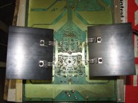
A bit skeptical the smaller FJP has the same die, usually it's shrunk to lower cost in a smaller package and if you can't get rid of the heat long-term, what's the point of a big die.
Pic makes me wonder if it would even fit in a TO-220.
Wakefield Series 120 silicone thermal compound 0.5°C/W
Sil-Pad 900S 4.0 to 2.5°C/W (10-100PSI)
Mica 1.2°C/W
Otherwise, the thermal resistance of the mounting hardware is much greater than any package (TO-220 vs 264) difference.
A bit skeptical the smaller FJP has the same die, usually it's shrunk to lower cost in a smaller package and if you can't get rid of the heat long-term, what's the point of a big die.
Pic makes me wonder if it would even fit in a TO-220.
Wakefield Series 120 silicone thermal compound 0.5°C/W
Sil-Pad 900S 4.0 to 2.5°C/W (10-100PSI)
Mica 1.2°C/W
Attachments

Member
Joined 2009
Paid Member
That die wil fit in a TO-220, but barely. I haven't seen the inside of the FJP, but I have broken open some "300W" TO-220 hexfets. The die covers almost the entire tab, and there is barely any overmold coverage. I bet the MSL rating is poorer.
Grabbed
A TO-220 does around 1C/W with mica/goop and decent clamping to the heatsink.
You'd have to really make an effort to get it lower than that (TO-220s are not always flat e.g.)
Routinely mounting can easily lead to 1.5C/W.
Thermal resistance between case and heatsink drops to about 0.25C/W by using a Keratherm 86/82 insulator (plus clamping, not screw mounting).
In 1997 I did a 50W CFP amp with TO-220's.
They were direct mounted, no mica, greased up good, and the sink was fan cooled.
It worked well on ±30V into 4Ω.
Under severe stress testing, 10dB into clipping using FM music, the transformer eventually burned up.
They were direct mounted, no mica, greased up good, and the sink was fan cooled.
It worked well on ±30V into 4Ω.
Under severe stress testing, 10dB into clipping using FM music, the transformer eventually burned up.
100W/8 monaural power amp with 2 pairs of 75W vertical MOSFETs.
N- and P-channel pairs mounted without mica on a separate heatsink (<1C/W), heatsinks inside the amp case.
A common problem with this serial production item was blown BD139/BD140 drivers (mounted on the board without any heatsinks)
Never heard/read of blown output device examples, despite that the TO-220 pairs ran without source resistors, plus 40.000uF per rail.
Attachments
Last edited:
I am wondering if the Fairchild devices use smaller dies than the TOSHIBA ones...........
Regardless of the difference between the TOSHIBA 2SC200 and the Fairchild FJP5200, I am sure if you were to solder two FJP5200 TO220 devices to a large piece of copper the same size as a TO-264, with the same thickness, wire them in parallel, you would have a custom transistor that would outperform a single TO264, with almost double the current handling and a higher power rating.
Regardless of the difference between the TOSHIBA 2SC200 and the Fairchild FJP5200, I am sure if you were to solder two FJP5200 TO220 devices to a large piece of copper the same size as a TO-264, with the same thickness, wire them in parallel, you would have a custom transistor that would outperform a single TO264, with almost double the current handling and a higher power rating.
Last edited:
A misnomer if I ever saw one, the LM3886/TDA7294/etc. is twice the size of a TO220 , was it so hard to assign it a new number?TO-220 11-pin
TO220 5 pin is correct (TDA20xx)
And the point is, this actually "double TO220" case can not be compared to the real ones.
- Status
- Not open for further replies.
- Home
- Amplifiers
- Solid State
- TO-220 output transistors for power amp