eranrund said:Updated schematics, please share your insights.
An important thing - the 10K bleeder resistor, resulting in current of around 25mA - is that sufficient?
Thank you all again and again for your time and energy reviewing these things..
R6 would be dissipating 6W! Also, you have 40mA through the regulator, and you haven't even connected the preamp yet! That will create an awful lot of wasted heat.
You already have 15mA flowing through R2 and R3. They should be plenty to drain the caps when the power is turned off.
For audio apps a cap from adj to ground may be a good idea -- transient performance is traded off vs noise.wakibaki said:
I wouldn't put a cap from ADJ to ground, the datasheet specifically recommends against. You can always leave room for it to try later if you feel the performance is lacking, but right now it's just another thing to go wrong.
jackinnj said:
For audio apps a cap from adj to ground may be a good idea -- transient performance is traded off vs noise.
If you do that, add a diode from the adj pin (anode) to the output (cathode).
MrTransistorm said:If you do that, add a diode from the adj pin (anode) to the output (cathode).
As you can see from this comment, this capacitor takes you into unknown territory.
Just try to follow the instructions in the datasheet for the moment.
w
I will skip the capacitor/diode for now.
About the 470 resistor (R1) - is it really necessary? 2Watt aren't gonna cut it, are they?
About the 470 resistor (R1) - is it really necessary? 2Watt aren't gonna cut it, are they?
Yes, get rid of the resistor. If you pull 125mA thru it it will dissipate 7+Watts. You only really need 1 100u cap, the other one is redundant, and since the regulator is very close to the remaining cap the 10u is unnecessary too, although neither are doing any harm.
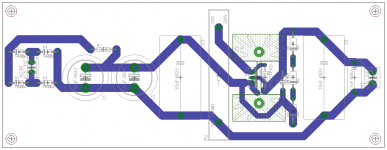
Other than that your layout is fine, but try to arrange your tracks so as not to reduce the spacing between the regulator pads; either offset the outside track's centreline so that the track does not creep into the pad-pad space or reduce the track width. If you maintain 40 thou between conductors it should be more than adequate for the voltages you are running. If you are concerned that the tracks are too thin you can find recommended widths versus copper weights for a given current on PCB manufacturers' sites. In general, component manufacturers will provide a package which can be connected adequately without heroic efforts.
You should avoid joining tracks where it results in an angle < 90 degrees such as where the track from R1 meets the track joining the 2 100u's. This is a minor point but keeping the track outline smooth means that there is less likelihood of a defect in manufacture and such things become more critical at high frequencies so this is a good habit to cultivate.
w
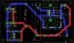
So it took a while for me to get back to this project, but here is a revised layout.
Would this do the job?
Remember input is 220-240v AC, and output is expected to be 250V
This is the first time I am working with such high voltages, and to be honest, I am quite scared of screwing something up.
My capacitors are rated >350v. Should any special resistors be used for these voltages? Are all my traces spacing fit?
Many thanks
Attachments
eranrund said:
This is the first time I am working with such high voltages, and to be honest, I am quite scared of screwing something up.
My capacitors are rated >350v. Should any special resistors be used for these voltages?
Many thanks
Your Cap ratings are more than sufficient for the job at hand.
Resistor values depends on the Amps/Volts= Watts through them so "special resistors" ? No, appropritate sized wattage? yes.
Ron
1. Loose the 10uF input film cap.
2. Put a 2w to 5W, 470 Ohm (Value depending on your input voltage and if there's still some voltage drop on your regulator, to work properly) between C1 and C2 positive.
3. Make a trace from negative of D3, D4 to negative of C1 then negative of C2 and from there to R2 and the rest of your circuit.
4. Layout could be easily rearranged for single sided PCB.
5. Maybe it's a good idea to make a provision for a low value resistor from regulator output to top of the output film capacitor. (Only one 10uF cap at the regulator output should be enough, put the 0.1uF cap closer to your amplifier)
Thank you for the replies.
Regarding gagnou's comments
1. So I thought, I'll get rid of it
2. What is the purpose of this resistor? Current limiting when the thing is powered up?
3. Will do
4. As I do not pay extra for double layer, this isn't much of a concern. However, what got me into the two layers was more a matter of increasing the distance between tracks than anything else. Does it matter?
Also, on the same subject, would I benefit from a ground-plane on one of the sides?
5. What purpose would this resistor serve? Protect the regulator from high charging currents of the 10uF resistor?
Partially yes although the regulator shouldn't be in trouble with those big electrolytics in the input.2. What is the purpose of this resistor? Current limiting when the thing is powered up?
I consider this resistance together with the zeners is providing a better protection to the regulator in case of an output short.
I never thought it that way but of course you're right.However, what got me into the two layers was more a matter of increasing the distance between tracks than anything else. Does it matter?
Having two points, with 250 (or more) volts difference between them, close together in a PCB is potentially dangerous.
No.5. What purpose would this resistor serve? Protect the regulator from high charging currents of the 10uF resistor?
The inductive output impedance of the regulator forms with the film output cap a high Q resonance at some frequency.
The series resistor (usually 1 to 2 ohms) helps to dampen this resonance and avoid ringing or oscillations at the output.
The output of the regulator remains the middle pin of TL783.
From there to ground goes the series combination of R1 and C5.
Sorry if I wasn't clear before.
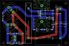
R4 is going to put out some heat also so a little space between it and C1, C2 would be a good idea.
Try to keep the regulator OUT and GND traces further apart.
You could also try rotating the right hand part of the layout starting from R2, 90 degrees CW. This could result in smaller loop of circulating currents and would also put heat producing R2 at the edge of the board, away from C1, C2.
Last and from a practical point of view regarding connections it's better to have connecting terminals at the periphery of the board clear of any obstructions.
From there to ground goes the series combination of R1 and C5.
Sorry if I wasn't clear before.
R4 is going to put out some heat also so a little space between it and C1, C2 would be a good idea.
Try to keep the regulator OUT and GND traces further apart.
You could also try rotating the right hand part of the layout starting from R2, 90 degrees CW. This could result in smaller loop of circulating currents and would also put heat producing R2 at the edge of the board, away from C1, C2.
Last and from a practical point of view regarding connections it's better to have connecting terminals at the periphery of the board clear of any obstructions.
So you mean both the R1-->C5 and the Terminal block should be connected to the regulator's output (Instead of having both C5 and the Terminal block go through R1)?
I'll attempt rotating it during the weekend, we'll see how it goes
Thanks again
I'll attempt rotating it during the weekend, we'll see how it goes
Thanks again
Correct.
TL783 OUT goes to output terminal.
R1 goes to output terminal.
C5 goes to other side of R1 and to GND.
You could also check this:
http://www.national.com/an/LB/LB-47.pdf
Regards,
George
TL783 OUT goes to output terminal.
R1 goes to output terminal.
C5 goes to other side of R1 and to GND.
You could also check this:
http://www.national.com/an/LB/LB-47.pdf
Regards,
George
eranrund said:Anyone?
I'm eager to send this to a PCB manufacturer already 🙂
I wouldn't be too eager... I strongly advise you to actually breadboard and carefully check this circuit in real life conditions (with the real load it is intended to work with) before placing any quantity PCB manufacturing order. I don't know if T.I changed the internal circuit topology of the TL783 since it's introduction (around 1980) but I remember I had very bad experiences then with this circuit which was extremely unstable and oscillation-prone. I tried all the possible tricks (by-passing or not,shortest possible circuits layouts,etc...) strictly adhering to T.I design considerations,all to no avail: the circuit would sproradically break into heavy oscillation (usually putting out a nice sawtooth of about 50~100 Hz) at any unpredictable moment. (could be a few hours to many days) Despite all my attempts I never suceeded to cure this fault which seemed inherent to the circuit used (TL783) and I finally gave up. (And went back to all-tube regulation which never gave me any troubles so far). Since then I debugged many D.I.Y preamplifiers plagued with "intermittent hum problems" for friends and each time the culprit was... (you guessed it) the TL783 used in the power supply ! Usually the fault is very intermittent and an oscilloscope is needed to monitor the regulated B+ line . The only attractive point (for tube circuits lovers) of the TL783 is his (relatively) high (125V) Vi-Vo voltage differential but otherwise it is a lousy regulator which I would never use in any high-quality audio design. Use your own discretion but also consider other alternatives (there are many).
My bad, interesting point...
Considering this is my first tube project (6922 preamp), perhaps anyone could provide a suggestion for a different regulated PSU that does not involve tube regulation or chokes. I want to cut on expenses on the first stage, see if I even get the thing to play audio at all before I start investing more money in this project.
Considering this is my first tube project (6922 preamp), perhaps anyone could provide a suggestion for a different regulated PSU that does not involve tube regulation or chokes. I want to cut on expenses on the first stage, see if I even get the thing to play audio at all before I start investing more money in this project.
- Status
- Not open for further replies.
- Home
- Amplifiers
- Tubes / Valves
- TL783 regulated B+ 250V PSU schematic