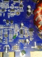
Hi i need to know if i can set a tl494 voltage higher on a amp as its voltage stays on 4v unloaded and drops down to 2v loaded the switching is there and voltage drop seem too extreme. It only happens when i fit the power supply fets in other than that its ok.
Any ideas will be much appreciated.
Thanks
Any ideas will be much appreciated.
Thanks
Is the voltage dropping on pin 12?
What do you mean by 'loaded'?
Is the voltage due to the power supply being regulated and the pulse width is reduced when driving FETs?
What do you mean by 'loaded'?
Is the voltage due to the power supply being regulated and the pulse width is reduced when driving FETs?
No voltage drop on pin 12 and by loaded i mean output fets in the amp. Pin 12 stays at 9v no matter if i even put a 12v supply on. I will have to check the duty cycle
Post a photo of the component side of the main board and the component side of any driver boards.
To clarify, are you saying that pin 12 (what about 8 and 11?) is regulated to 9v no matter how much B+ voltage you apply to the amp?
9v?
Do you have a scope?
Please (and this applies to anyone who needs repair help) use your sig line to list all equipment you have, editing it as equipment changes. Include the model numbers.
Top of page, menu USER CP >> EDIT SIGNATURE
Oscilloscope (yes or no)
Multimeter(s)
Type of signal source (grounded RCA shields preferred).
Soldering iron
Desoldering pump
Power supply
2 ohm current limiting resistor (hollow cylindrical ceramic 100w preferred)
No voltage drop on pin 12 and by loaded i mean output fets in the amp. Pin 12 stays at 9v no matter if i even put a 12v supply on. I will have to check the duty cycle
Supplying 12V to the controller and having it drop out at 9v the output of the said controller will have BJT buffers that will be driven from this weak 9V drive source (open collector) 200mA(Max) complementary mode, and by the time this buffered signal reaches the bank of gates (Vgs) the Vgs should be equal to 13v/12v/14v just enough for the fets to "softly saturate" as a power switch.
However:
What's interesting during power FET destruction analysis of a car amplifier the lower Vgs drive the more ohmic (linear) the mosfet device acts as a "big power resistor" P = (R * V ^2) and dissipates alot of heat eventually/instantaneously destroying the bank of power fets.
I wish manufacturers created a boost circuit of 20V (unregulated) that will force a drive signal Vgs of 15V @ 2A (regulated) throughout the life cycle of the amplifier (irrespective of battery supply voltage or aging conditions), the amplifier protection are only half measures for UVLO (under voltage lock out) by then fets are already internally damaged with parameters drifted by 30% from its spec.
Last edited:
- Home
- General Interest
- Car Audio
- Tl494 output voltage
