Hello
as you see this image,vout is equal :
)

but in SMPS circuit i see something interesting.

Vout=2.5(1+47.5/2.7)=46.48
another one

Vout=2.5(1+12000/100)=302.5
if i change the R1 and R2 in this equation i have these result
Vout=2.5(1+2.7/47.5)=2.64
Vout=2.5(1+100/1200)=2.708
it means if output voltage is fix on the desire volt it has error !!!!
why?
what is my fault?
Please tell me how the Tl431 work in SMPS circuit?
and more question that i asking myself
1-it means we calculate the R1 and R2 with output voltage and find the output voltage of Tl431 with VTl431=2.5(1+R1/R2)?
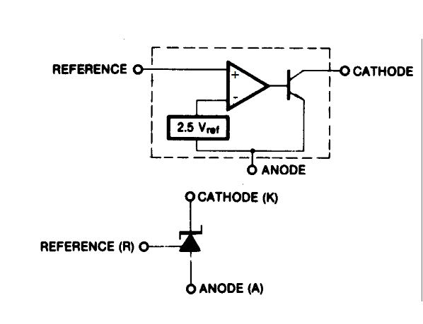
2-it means if the Pin Reference=2.5 the output of Tl431 is equal 0 according below schematic?

or
output Tl431 is equal to VTl431=2.5(1+R1/R2)
-------------------
i create this schematic circuit

V Pin 3 to ground=1.91
Vref pin 1 to ground=2.54
what is my fault?is it not the similier circuit to SMPS feedback output?
but it works fine

V Pin 3 to ground=5.2
Vref pin 1 to ground=2.54
as you see this image,vout is equal :

but in SMPS circuit i see something interesting.
Vout=2.5(1+47.5/2.7)=46.48
another one
Vout=2.5(1+12000/100)=302.5
if i change the R1 and R2 in this equation i have these result
Vout=2.5(1+2.7/47.5)=2.64
Vout=2.5(1+100/1200)=2.708
it means if output voltage is fix on the desire volt it has error !!!!
why?
what is my fault?
Please tell me how the Tl431 work in SMPS circuit?
and more question that i asking myself
1-it means we calculate the R1 and R2 with output voltage and find the output voltage of Tl431 with VTl431=2.5(1+R1/R2)?
2-it means if the Pin Reference=2.5 the output of Tl431 is equal 0 according below schematic?
or
output Tl431 is equal to VTl431=2.5(1+R1/R2)
-------------------
i create this schematic circuit

V Pin 3 to ground=1.91
Vref pin 1 to ground=2.54
what is my fault?is it not the similier circuit to SMPS feedback output?
but it works fine

V Pin 3 to ground=5.2
Vref pin 1 to ground=2.54
The wrong in your think is that in a secondary side regulation from a SMPS, the TL 413 is used not as voltage shunt regulator, but as voltage controlled current source for the led in a photoupler (Or photoisolator). You must calculate the current trough the led diode, nor the voltage.
Your problem is that you are looking at multiple output curcuits using weighted feedback networks that have a dominant (main) output and include a limited amount of feedback from the auxiliary outputs to improve their cross regulation. The output you chose for your calculations was one of the aux outpuits with only a small contribution to the total regulation (read big feedback resistor), so you got a nonsense result. If you had chosen the master output for your calculation, you would have gotten a number much closer to the number for a single output case, but a litte higher. In the case of the first example, that possibly would have been the +5V output.
For a single output situation you can indeed predict the output voltage of the supply from the simple equation. It is true that the TL431 controls the output voltage via the current it pulls through the optocoupler, but since that is inside the loop and the open loop gain of the TL431 is very high, this does not enter into the basic equation for output voltage.
The value of resistor in series with the optocoupler is important in that it determines the mid-frequency gain of the control loop. Too small, and the supply might be difficult to stabilize. Too large, and the power supply may not have enough control range to regulate at light/zero load.
Also remember that a TL431 need 0.5-1 ma bias current to run properly (it's right there in the data sheet). A ~1k resistor should be placed across the optocoupler LED to provide that bias current without turning on the LED, otherwise you might see some funny results for regulation.
Hello
Thanks so for your replay
i found my problem and appreciate
(this forum doesn't have thanks button)?
Thanks so for your replay
i found my problem and appreciate
(this forum doesn't have thanks button)?
Dear wrenchone
could you tell and introduce me a good reference about SMPS circuit that i can design and realize how they work?
Thanks
could you tell and introduce me a good reference about SMPS circuit that i can design and realize how they work?
Thanks
Try Pressman's SMPS book (2nd or 3rd ed.). I was nurtured on the 1st ed (I'm an old guy), but later editions have more to say about stuff that actually matters these days. There are other texts, but they may be overly pedantic/too much concerned with math rather than actual circuits - don't get me started on that topic. The Pressman book will be a start, at least.
Last edited:
I also have the Marty Brown (I don´t remember if the name is well written), and it is also o good Book. In act, I buy this first, and second the Pressman´s one.
 I think this thread would be of more relevance in the power supply forum, so I will move it there.
- Status
- Not open for further replies.
- Home
- Amplifiers
- Power Supplies
- TL431 Problem in SMPS circuit