I don't see much problem as it shouldn't make much difference wether you regulate the 'voltage' or the 'ground'. Both are electrically just potentials.
However, I have that series connection also seen in a Linear Technology datasheet, so it's not exotic.
Have fun, Hannes
PS: don't worry about the LT1083. It should work with your TL431 too.
However, I have that series connection also seen in a Linear Technology datasheet, so it's not exotic.
Have fun, Hannes
PS: don't worry about the LT1083. It should work with your TL431 too.
AndrewT said:All push pull ClassA topologies are not constant current.
Not True. Consider a Tube push pull class A circuit.
Chris
lineup, thanks for your schematic, i am reading and try to understanding now.
H.A, thanks for reply, i still not understand the two postive dc added together to form a dual supply, i will think on it. 🙂
PMA,i think it's different, in u schematic tl431 act as a Zener(better temperature performance than normal zener)
H.A, thanks for reply, i still not understand the two postive dc added together to form a dual supply, i will think on it. 🙂
PMA,i think it's different, in u schematic tl431 act as a Zener(better temperature performance than normal zener)
This JLH circuit and most ClassA single ended topologies are not constant current.
All push pull ClassA topologies are not constant current.
I and some others are aware of the few exceptions that are truly constant current (within the limits of amp linearity).
Many wrongly attribute the general characteristic that ClassA are constant current. They don't realise that the rails supply a modulated current that varies with the output current and can approach the range of near zero to double the bias current until the amp enters ClassAB if that's possible.
All push pull ClassA topologies are not constant current.
oops there's an almost missing from that last line.Chris Jennings said:Not True. Consider a Tube push pull class A circuit.
I and some others are aware of the few exceptions that are truly constant current (within the limits of amp linearity).
Many wrongly attribute the general characteristic that ClassA are constant current. They don't realise that the rails supply a modulated current that varies with the output current and can approach the range of near zero to double the bias current until the amp enters ClassAB if that's possible.
H.A, thanks for reply, i still not understand the two postive dc added together to form a dual supply, i will think on it.
It works the same way as you would put 2 Zeners in series - it's just a series connection of 2 regulators with your reference "ground" in between.
Have fun, Hannes
I notice in the Kwak clock 7 schematic there's a 100 pf cap between cathode and reference pins of the TL431 in the positive series regulator, but no corresponding cap in the negative one. Is this an omission or is it supposed to be that way?
If you gave us a clue as to what a "Kwak clock 7" was and posted a schematic, link to schematic or just a circuit diagram, someone might be able to reply. 🙂
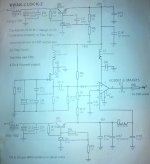
Its clear the negative regulator has been formulated differently - there's no feedback. Presumably the 100pF cap on the positive one is to maintain stability as it has feedback. Notice R8 and R9 have to be set to give roughly -5.6V on the PNP's base to get -5V output.
- Status
- Not open for further replies.
- Home
- Amplifiers
- Solid State
- TL431 pos & neg regulator