Hi!
Does anyone have a good design "guide" for the TL431 based voltage feedback through an opto-coupler, in switched mode power supplies?
I "talking" about the resistors' values. About what criteria do I choose the optocoupler led's current, the TL431's current, what parameters do I have to check in the optocoupler's datasheet, when I choosing one, how can I properly implement the optocoupler's transistor at the PWM controller IC, etcetcetc....
Does somebody has a design help, about the above topic?
You could check the datasheet of LT1509 power factor correction switched power supply, from www.linear.com
http://www.linear.com/pc/productDetail.do?navId=H0,C1,C1003,C1142,C1138,P1516
http://www.linear.com/pc/downloadDocument.do?navId=H0,C1,C1003,C1142,C1138,P1516,D1119
http://www.linear.com/pc/downloadDocument.do?navId=H0,C3,P1512,D1003
Check also the application note for more info.
http://www.linear.com/pc/downloadDocument.do?navId=H0,C3,P1512,D4348
The TL431 is a jewel of a product -- extremely inexpensive -- but like all opamps it has its reactive components which require compensation -- i've mentioned this article in EDN a few times --
http://www.edn.com/contents/images/6255051.pdf
i've used the TL431 as a tempco stabilized comparator in addition to its typical applications.
http://www.edn.com/contents/images/6255051.pdf
i've used the TL431 as a tempco stabilized comparator in addition to its typical applications.
Danko,
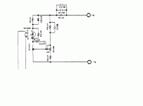
The circuit I showed also has compensation for the PWM and not just the TL431. Post if you would like some help with the equations.
😉
The circuit I showed also has compensation for the PWM and not just the TL431. Post if you would like some help with the equations.
😉
Aaaaaand, what about the PWM-controller IC? How do I choose the pull-down resistor? I just pick a current (for example, 1mA), and depending on the optocoupler's collector-voltage, I just use Ohm's Law, R=U/I ? Where U is for example 12V, the pwm-controller IC's powersupply.
The key to understanding the TL431 circuit is to assume the voltage at the junction of R110 & R111 is constant. The circuit is a voltage to current converter.
The transistor in the opto can be used for pull-up or down... What PWM chip are you using?
The transistor in the opto can be used for pull-up or down... What PWM chip are you using?
Look at http://powerelectronics.com/mag/50107.pdf also - the EDN article quoted above has no separate bias resistor, which this article recommends.
- Status
- Not open for further replies.
- Home
- Amplifiers
- Power Supplies
- TL431 design guide
