Quiescent current is 4ma per amp and max output current 35ma per amp hence 4x(4+35)=156ma max are required from the Iccs.
I don't think you need to consider maximum output current of 35mA per amp - that's where you calculate the actual load on each amp, which for a good design should be under 3mA per. And if an amp does get overloaded (accidental short circuit on the output for instance) limiting the power supply isn't all that bad of a situation anyway. So I doubt your practical power supply requirement will exceed 30 mA total. Now you are dealing with a 15*0.03 = 0.5W transistor dissipation as a maximum. This should be a simple design with a SOT-23 transistor.
7W or 10W would be more sensible............... it will dissipate 15V*0.156A=2.34W at that condition (max). So it's probably prudent to go for a 3W spec transistor or more.
temperature de-rating takes a lot out of the power capability.
I don't think you need to consider maximum output current of 35mA per amp - that's where you calculate the actual load on each amp, which for a good design should be under 3mA per.
What determines what is a good or a bad design?
In my case I am going to create an instrumentation amp to feed an LM3886, pretty much like this:
http://en.wikipedia.org/wiki/File:Op-Amp_Instrumentation_Amplifier.svg
with R1=1K , R2=R3=2K
500Kohm resistors will be also connected between each input to ground.
Source is going to be either a CD player or DAC.
So in this case how do we calculate the loading on each opamp?
What is the peak output current into the resistive and capacitive load?
Could the worst case audio signal occur at the same time for all opamps, i.e. could they all draw peak current at the same time?
Could the worst case audio signal occur at the same time for all opamps, i.e. could they all draw peak current at the same time?
I suppose with those values you could source as much as 15mA per, but then again using 1K and 2K resistors is not the best design. Go 10K and 20K; functionally it will work the same and your power requirements are cut by a factor of 10. Amplifier will be happier, too. Now you can assume 1.5mA per (this is just the load current portion).
So the assumption of 3mA per will be sufficient, just keep your load resistors around the 10K range.
So the assumption of 3mA per will be sufficient, just keep your load resistors around the 10K range.
thanks for the good advice
Re CCS design, is my logic correct in terms of R3 and Rcl calculation (post 17) ?
Re CCS design, is my logic correct in terms of R3 and Rcl calculation (post 17) ?
I suppose with those values you could source as much as 15mA per
By the way how do you know / calculate that?
Cheers
Another question, which might be a stupid one, is how do I "invert" the CCS for use on the negative rail? See attached option 1 - i have just flipped the transistor from NPN to PNP. Would that work?
Also see option 2 vs option 3 in case of LM317/337 based CCS. Would option 3 work with the LM317 just rotated around, or LM337 is necessary as per option 2 ??
Also see option 2 vs option 3 in case of LM317/337 based CCS. Would option 3 work with the LM317 just rotated around, or LM337 is necessary as per option 2 ??
Attachments

Last edited:
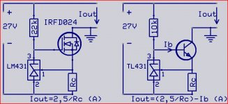
Well I think you shoud do it like this.The MOS solution is the best.
Mona
Thanks for that. Interesting design. We are slowly making it look more like the salas shunt 🙂🙂
Why is MOSFET better than BJT?
Also I note you have used a 10K on top of your BJT in your second option, I am using 5k, but how do you select that value?
Last edited:
Another question, which might be a stupid one, is how do I "invert" the CCS for use on the negative rail?
You don't need to. Go back to post #3 schematic. You only need one CCS.
Well I think you shoud do it like this.The MOS solution is the best.
Mona
I just realised our schematics are actually very different and I think I may have made a mistake.
I have used the constant current LIMITER design from the TL431 datasheet. Whereas here we need a constant current SOURCE. Is that the same thing?
The TL431 datasheet also has a design for a constant current SINK. That is closer to Mona's circuit.
I am getting confused....😕
Have you looked at the schematic in post #3 ?
You only need one CCS for a bipolar power supply. This assumes you have a dedicated transformer for the raw DC input.
I would not get too worked up about the quality of the supply and using the best possible parts you can. Absolutely nothing wrong with bipolar for this application; the pursuit of MOS is a diversion you don't need. Your lack of knowledge in how to determine power supply load testifies that you should start simple and learn as you go. Just taking sample circuits from the TL431 datasheet and putting parts together can function, but don't try to tweak and go for ultra-low noise until you understand fully how to design all this yourself.
Have you looked at the schematic in post #3 ?
You only need one CCS for a bipolar power supply. This assumes you have a dedicated transformer for the raw DC input.
I would not get too worked up about the quality of the supply and using the best possible parts you can. Absolutely nothing wrong with bipolar for this application; the pursuit of MOS is a diversion you don't need. Your lack of knowledge in how to determine power supply load testifies that you should start simple and learn as you go. Just taking sample circuits from the TL431 datasheet and putting parts together can function, but don't try to tweak and go for ultra-low noise until you understand fully how to design all this yourself.
And I am the first to admit my understanding is limited hence with all the questions. And by the way I appreciate all the help from all the people here.
Again it is a learning exercise for me wanting to understand what is the role of each of the bits and bobs.
I do want to stick to the original brief until we exhaust it / understand it. If someone can explain how the whole thing works (in simple english) I would be very gracious. And hopefully others can also learn.
I agree about bipolars I don't want to change them. I want to stick to the original brief. But people naturally suggest other options which is fine, but I do ask the whys. E.g. why is MOSFET better than BJT. Not saying I will use them but just asking why out of curiosity.
Re part choice I just want to learn what are the important selection factors and not just get given are the best possible parts. That's why I am trying to work out the logic through calculations.
I have looked at post 3 and I have noted there is only one CCS indeed. Both instrumentation amp and poweramp in my case will share 1 traffo. So I respectfully think a CCS is also needed in the negative rail. Please feel free to argue otherwise.
I do understand the basic shunt based on one TL431+no transistor & simple LM317+1 resistor CCS. That is my baseline, I think the next step up in complexity should be the one in post 1.
Cheers!

Last edited:
- Status
- Not open for further replies.
- Home
- Amplifiers
- Power Supplies
- TL431 Based CSS & Shunt Reg for +/-15V