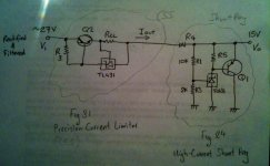
I have been looking at the TL431 datasheet so I was thinking about combining a CSS and a Shunt Reg from figures 31 & 24 respectively to get a precise +/-15V regulator (see attached).
Do we think the concept would work?
I am planning to power between 2 to 4 opamps with this supply with input from a 20v-0-20v traffo rectified & filtered.
Do we think the concept would work?
I am planning to power between 2 to 4 opamps with this supply with input from a 20v-0-20v traffo rectified & filtered.
Attachments
Interesting design I like it. But I would like to stick to the original briefing (with the transistors included) for learning purposes and also I might decide to use the PS on higher current applications.
I note you set your CSS for 20ma. How do you decide that? Do you base it on e.g. the maximum expected current your load is going to draw + a contingency margin?
In my case I want to power opamps. How do I estimate how much current they are going to draw?
Do we base it on the quiescent current of the opamp i.e. 5ma / opamp?
That is probably too low anyway for the transistor, it probably need to be in the 1A region to get the Q moving (I plan to use medium power transistors).
Last edited:
It's a very stable and reliable design, capable of working with a large swing of raw dc input.
Yes, you select the CCS current to be the maximum expected load current plus the minimum desired shunt regulator current (which is spec'd at 1mA). If the load draws less than expected, the shunt takes the balance (in the limit, the shunt should be capable of sinking the entire CCS current). This helps you design for heat dissipation and the potential requirement for a pass transistor.
I normally look up the opamp datasheet and add up the quiescent current specs. Then, I look at how heavily I load each opamp, and add that current to the pot. Maybe a little extra margin for good measure, and that's about it.
I don't understand; why do you want a 1A regulator for a few opamps? Just to learn? Why not toss in a TO-92, TO-225, or TO-39 instead? Principles are the same, just a part better selected to handle the application.
Thanks mate useful answers
What do you mean by that? Do you mean (Iout - In) of the opamp + the quiescent current Idd in order to get the overall draw of the opamp for CCS calculation?
Yes 1A is not required for this opamp application but I do still want to learn how to calculate Q1 & R5. Let's try that! If say I use the 2N2907 in place of Q1, is it going to work? And how do I calculate the R5 / how do we need to bias Q1?
Then, I look at how heavily I load each opamp, and add that current to the pot
What do you mean by that? Do you mean (Iout - In) of the opamp + the quiescent current Idd in order to get the overall draw of the opamp for CCS calculation?
I don't understand; why do you want a 1A regulator for a few opamps? Just to learn? Why not toss in a TO-92, TO-225, or TO-39 instead? Principles are the same, just a part better selected to handle the application.
Yes 1A is not required for this opamp application but I do still want to learn how to calculate Q1 & R5. Let's try that! If say I use the 2N2907 in place of Q1, is it going to work? And how do I calculate the R5 / how do we need to bias Q1?
Last edited:
The load on the amp depends on what signals you are driving, and into what size resistor. For instance, if the amp is pushing a 5V signal into a 10k resistor, you require an additional 0.5 mA over and above the datasheet quiescent current. Take a look at each amp and what it drives.
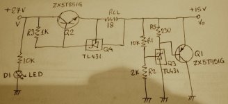
For starters on your design, if you are using a CCS upstream you don't require R4. You use the CCS to absorb the unneeded voltage from the source. With 27V in and 15V out, you have 12V to drop. You can either have Q2 drop all this voltage (which will dissipate watts based on the current setting) or add R4 to take some of the heat. All depends on your heatsink design.
R5 is chosen by the following procedure: The base-emitter junction is ballpark around 0.7V, regardless of current. So you chose the resistor size to keep the TL431 well into a happy regulation region, say 3mA. So R5=.7/3mA = 230 ohms. The TL431 will also sink the base current from Q1, so as another ballpark Ib=CCS/beta (I like to assume worst case load dump conditions). You can do the math on this, just be aware the TL431 must sink the sum total current. If this current is too large you may have to migrate to a darlington transistor.
Then it's a matter of checking all the heat dissipation in each component, making sure you don't run into problems.
into the resistor and the capacitor.The load on the amp depends on what signals you are driving, and into what size resistor. ........
The current into parsitic capacitance is likely to be quite low, but deliberately added capacitance can draw very high currents from the supply, via the opamp output.
R5 is chosen by the following procedure: The base-emitter junction is ballpark around 0.7V, regardless of current. So you chose the resistor size to keep the TL431 well into a happy regulation region, say 3mA. So R5=.7/3mA = 230 ohms. The TL431 will also sink the base current from Q1, so as another ballpark Ib=CCS/beta (I like to assume worst case load dump conditions). You can do the math on this, just be aware the TL431 must sink the sum total current. If this current is too large you may have to migrate to a darlington transistor.
Interesting. So the choice of R5 is almost unaffected by the choice of Q1.
To work with a specific example say I choose Q1=BC807 (did I mention I like surface mount parts and no heatsinks) and R5=230 ohm.
So the Vc=15v, Ve=0v and Vb=Ve+0.7V=0+0.7=0.7V. Is that correct?
The current across R5 will be Vr5=15-0.7=14.3V hence Ir5 = 14.3/230=62ma.
That then will split into Ika through the TL431 and Ib i.e Ika+Ib=62ma.
How do i then calculate either of them?
Last edited:
I think I got it. Looking at the BC807 datasheet, for a Vce=Vc-Ve=15v-0v=15v we can only get Ic=90ma with Ib=0.35ma.
Hence at that condition (and assuming Iref of the TL431 = ~0 and Ir1=15v/12kohm=1ma=~0) the current needed from the CCS will be Iccs=Ic+Ir5=90+62=152ma.
The power dissipated by Q1 will be Pq1=Vce*Ice=15v*0.09A=~1.5W. That far exceeds the max power dissipation of the BC807 310mW so it'll blow up without a heatsink....
Have i got all that lot right?
The Ic=90ma feels too low for the capabilities of BC807, we can get more Ic if the voltage drop Vce is much less, e.g. 1V. We can achieve that by adding a resistor between emitter & ground, correct?
Last edited:
The current across R5 will be Vr5=15-0.7=14.3V hence Ir5 = 14.3/230=62ma.
No, the voltage drop across R5 is 0.7V, and with a 230 ohm resistor you get 3mA. It stops there.
Looking at the BC807 datasheet, for a Vce=Vc-Ve=15v-0v=15v we can only get Ic=90ma with Ib=0.35ma
I didn't look at the datasheet, but that is a beta of around 250 (seems a little high, but could be). If you want to be able to sink 1A, then your base current is 1/250 = 4mA. Now the TL431 will sink 3mA + 4mA = 7mA. No problem.
The Ic=90ma feels too low for the capabilities of BC807, we can get more Ic if the voltage drop Vce is much less, e.g. 1V. We can achieve that by adding a resistor between emitter & ground, correct?
Typically your transistor will have a greater beta as you increase its Vce headroom. So no, adding a resistor will not magically give you more Ic. The TL431 will sink as much current as it needs to in order to support 15V of regulation. The more current it sinks, the more base current is drawn from Q1, therefore Ic goes up. The limits are overall dissipation in each part and beta of Q1.
I think I got it. Looking at the BC807 datasheet, for a Vce=Vc-Ve=15v-0v=15v we can only get Ic=90ma with Ib=0.35ma.
No wait I got it wrong. There is no guarantee we will get Ic=90ma @ Ib=0.35ma, we could also get e.g. 50ma @ 0.2ma etc. What ties Ic & Ib down?
I am looking at Fig.6 here:
http://www.diodes.com/datasheets/ds11208.pdf
zigzagflux
Thanks mate I got it all wrong...... back to the drawing board! 🙂
Good learning. Quick question do you select Iccs first and then choose a suitable Q1?
For this example if BC807 sinks 1A peak (right at its limit) then Pq1 peak=15v*1A=15W right ?
That is well above its max dissipation spec 310mW, is that going to be a problem?
What would be a safe amount of current to sink through that transistor?
Last edited:
We are now back to post #2. The first step is to confidently determine your power supply requirements, and work from there. This is most critical with a shunt regulator from a thermal consideration. If you are truly looking for 1A to your load, you should ideally select a transistor that can shunt 1A for an extended period of time to accommodate load dump conditions. If you feel like designing a 1A power supply to drive a 15 mA circuit, all you will end up doing is burning a bunch of watts in silicon.
To answer simply, the transistor is limited by power, not current in this application.
To answer simply, the transistor is limited by power, not current in this application.
The shunt is ok as long as R5 is smaler then 600ohm to garantie the min.current for the TL431 (>1mA).What's the purpose of R4 ???
But the CCS stinks :-( (a hum-smell)
Iout=2,5/Rcl + I(R3).And that last part isn't stable at all 😱
Mona
But the CCS stinks :-( (a hum-smell)
Iout=2,5/Rcl + I(R3).And that last part isn't stable at all 😱
Mona
We are now back to post #2. The first step is to confidently determine your power supply requirements, and work from there. This is most critical with a shunt regulator from a thermal consideration. If you are truly looking for 1A to your load, you should ideally select a transistor that can shunt 1A for an extended period of time to accommodate load dump conditions. If you feel like designing a 1A power supply to drive a 15 mA circuit, all you will end up doing is burning a bunch of watts in silicon.
To answer simply, the transistor is limited by power, not current in this application.
Quite right.
I am planning to power one OPA4134 which has 4 opamps inside. Quiescent current is 4ma per amp and max output current 35ma per amp hence 4x(4+35)=156ma max are required from the Iccs.
In order for Q1 to sink that Iccs it will dissipate 15V*0.156A=2.34W at that condition (max). So it's probably prudent to go for a 3W spec transistor or more.
Last edited:
The shunt is ok as long as R5 is smaler then 600ohm to garantie the min.current for the TL431 (>1mA).What's the purpose of R4 ???
But the CCS stinks :-( (a hum-smell)
Iout=2,5/Rcl + I(R3).And that last part isn't stable at all 😱
Mona
I agree R4 is not required.
And I agree the CCS stinks, or rather its calculation! It does seem to require a few assumptions.
From TL431 datasheet R3=Vi/(Iout/hFE+Ika)
Assume Ika(ccs) = 25 ma
Assume hFE = 100
Then:
R3 = 27v/(156ma/100+25ma)=27v/(1.56ma+25ma)=1017ohm choose 1K resistor.
From datasheet Iout=Vref/Rcl+Ika i.e. 156ma=2.5v/Rcl+25ma thus Rcl=19.084 ohm choose Rcl=18 ohm.
That's all well and good but I have assumed Ika(ccs) = 25ma & hFE=100 completely arbitrarily. Is there any other equation that could help?
I am tempted to use zigzag's simple LM317 based CCS.
Last edited:
With the LM317 you have the same problem.A solution is to put it on the negative side or use a LM337.
Mona
Mona
With the LM317 you have the same problem.A solution is to put it on the negative side or use a LM337.
Mona
Not sure I understand that, what problem will I have with the LM317?
- Status
- Not open for further replies.
- Home
- Amplifiers
- Power Supplies
- TL431 Based CSS & Shunt Reg for +/-15V