Hi all,
I just replaced the TL072CN from my preamp with the "better" opa2134. The result is better highs more clear but the lows are not so punchy as with tl072cn. Is it me or this is the case? Any other experiances, or thoghts are welcome. Is this correct behaviour.
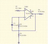
Attached the schematic.
I just replaced the TL072CN from my preamp with the "better" opa2134. The result is better highs more clear but the lows are not so punchy as with tl072cn. Is it me or this is the case? Any other experiances, or thoghts are welcome. Is this correct behaviour.
Attached the schematic.
Attachments
Have you tried to copy ( to draw ) the circuit from a piece of equipment or have you actually built it like the circuit shows 🙂
kzeprf22,
It seems the opa2134 uses at least twice as much current as the TL072. What does the power supply for the OpA look like?
Regards
It seems the opa2134 uses at least twice as much current as the TL072. What does the power supply for the OpA look like?
Regards
Thank you all for the answers.
The truth though is I done it a little bit quick this one, and I am thinking that something is wrong mechanicaly between the opamp base and the opamp. Maybe the opa is not conducting properly. I will check as soon as I find time and I will get back.
Thanks
What do you see wrong in the schematic. Is anything wrong?AndrewT said:check your schematic.
Both, It is a simple design that I builded many times. (non inverting amplifier)Mooly said:Have you tried to copy ( to draw ) the circuit from a piece of equipment or have you actually built it like the circuit shows 🙂
Probably, but in the equipment I have tested this the supply is about 100VA 30.000 uf capacitance, LM337/17 regulation bypass capacitors.Patrik Floding said:kzeprf22,
It seems the opa2134 uses at least twice as much current as the TL072. What does the power supply for the OpA look like?
Regards
The truth though is I done it a little bit quick this one, and I am thinking that something is wrong mechanicaly between the opamp base and the opamp. Maybe the opa is not conducting properly. I will check as soon as I find time and I will get back.
Thanks
if this is supposed to be a unity gain topology then far too many components have been fitted.
If it's supposed to be a gain of 1.9times (+5.6dB) then R2 is attached to the wrong node.
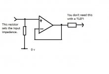
I think the output resistor of 75r is necessary since the tl07x series are reputed to be very bad at driving capacitive loading. The 75r should be located right next to the output pin of the opamp.
If R1=1k0 then it is there to minimise output offset by providing a resistive route for the input offset current. But 1r0 does nothing and even 1k0 will hardly change the output offset since tl07x are FET input opamps.
If it's supposed to be a gain of 1.9times (+5.6dB) then R2 is attached to the wrong node.
I think the output resistor of 75r is necessary since the tl07x series are reputed to be very bad at driving capacitive loading. The 75r should be located right next to the output pin of the opamp.
If R1=1k0 then it is there to minimise output offset by providing a resistive route for the input offset current. But 1r0 does nothing and even 1k0 will hardly change the output offset since tl07x are FET input opamps.
- Status
- Not open for further replies.
- Home
- Amplifiers
- Solid State
- tl072cn replaced by opa2134