jeapel said:ok 315v for vout but very important you need Iout(max) = ??
10ma or 100 ma or ??
Thanks for the reply
need 40ma in the output.
Hi John,
That's going to dissipate around 1.7W (just over), so you will need a heatsink for sure.
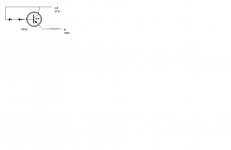
Right now you really only show a pass element. You need the rest of the circuit.
So you will have the 358 V in to the collector and take your 315 V from the emitter side. Have a look for some HV regulators (search). Regulators using an error amp will have much better performance than just a zener stack type.
-Chris
That's going to dissipate around 1.7W (just over), so you will need a heatsink for sure.
Right now you really only show a pass element. You need the rest of the circuit.
So you will have the 358 V in to the collector and take your 315 V from the emitter side. Have a look for some HV regulators (search). Regulators using an error amp will have much better performance than just a zener stack type.
-Chris
Hi jeapel,
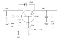
The 1N5408 could just as easily be a 1N4007 (cheaper). That circuit will work but I haven't calculated the dissipations. You may need a darlington hookup depending on delta I.
Why the devil do you need 40mA John? That is a lot, like 12 ~ 13 watts. Not enough for an output stage and too much for a preamp.
-Chris
anatech said:Hi jeapel,
The 1N5408 could just as easily be a 1N4007 (cheaper). That circuit will work but I haven't calculated the dissipations. You may need a darlington hookup depending on delta I.
Why the devil do you need 40mA John? That is a lot, like 12 ~ 13 watts. Not enough for an output stage and too much for a preamp.
-Chris
Trying to run a 45 on 215V with 32ma.
I still don't get how to use the TIP50 with different voltage.
Thanks John.
Hi John,
That's 315 volts, right? 😉
The transistor (TIP50 in this case) simply amplifies the current going into it's base. There is a voltage drop of 0.6 ~ 0.8 volts in that current range as a guess. Most people just call it a volt.
As long as you can maintain "X" number of volts at the transistor's base at the current required you should be good to go (within the ratings of the transistor). This would be [output current / transistor DC beta]. If you were drawing 40 mA and the beta was 10, you would need to supply 4 mA into the base and some down the zener string.
ALERT! If the load current drops to zero, the zeners now pass the standing current you designed plus the 4 mA. Make sure this will not overheat the zener string. If it will, add another transistor to lower the current variation in the zeners compared to the standing current in the zeners.
The above was just an example. You need to
look at the data sheets.
Clear as mud? 🙂
-Chris
One big problem with the article. Rated free air dissipation is rarely over 2 watts. You will need a heatsink for sure. Not a little tiny one either. Also, if the TIP50 is at minimum gain at some point, you will need 13 and change mA to drive it. Don't design so close to the edge. Use another transistor in darlington (emitter to base) to reduce the base current requirements.
Don't believe everything you read. 😉
-Chris
Don't believe everything you read. 😉
-Chris
Hi Anatech,
You are correct about that heatsink. I was just going to edit my post to state that. Thanks for being on top of things.
🙂 BC
You are correct about that heatsink. I was just going to edit my post to state that. Thanks for being on top of things.
🙂 BC
let me try this , to change the output voltage.
all I have to do is change the amount of zeners. right ?
Thanks John.
all I have to do is change the amount of zeners. right ?
Thanks John.
Hi BC,
Sorry. Quick out of the gate.
John,
Yes, change the value and/or number of zeners.
Do some math (important!). Figure out the min and max current requirements. Also plan for an open load (power on, no tube or open heater or heater supply). Calculate the dissipation on all the components and leave 5~ 10 X safety factor. Your ambient in the chassis will be higher than 25 °C. The answers are correct even if you don't like them. 😉
-Chris
Hi anatech,
No problem at all. I appreciate your thoroughness. 🙂 The use of the darlington configuration is solid. I have wanted to use that HV reg. for an S5 tube amp . I have just swamped myself with other projects. I have searched for a HV darlington that is commonly available, but a difficult find. Do you have any thoughts on a BJT that could feed the TIP50?
SORRY JOHN, I DID NOT MEAN TO STEAL THE THREAD!
I hope that this inexpensive HV Reg. circuit may help you, myself and others in the future. Sorry once again.
BC
An MPSA42 could be used as long as a series resistor is used to prevent the C-E voltage from exceeding 300V. There may be another device that can be used rated for a higher voltage. You do not need very much gain in this application.
This is on the same topic, so I don't see a thread jack here. Everything discussed benefits John as well.
-Chris
This is on the same topic, so I don't see a thread jack here. Everything discussed benefits John as well.
-Chris
I did not want to interrupt John's direction he seems to be taking for the reg. Thanks again Anatech. I was looking through some data books and thought the Zetex ZTX 658 might be a contender. However, I realize that it might not be accessible to the majority.
BC
Also found thatMouser sells an NTE replacement for the MPSA44 BJT (400V) and the Fairchild version of the 2N6517 (350V). Both of those are very inexpensive contenders.
BC
Also found thatMouser sells an NTE replacement for the MPSA44 BJT (400V) and the Fairchild version of the 2N6517 (350V). Both of those are very inexpensive contenders.
- Status
- Not open for further replies.
- Home
- Amplifiers
- Tubes / Valves
- TIP50 voltage regulator