Hello all
I've searched around for a series crossover designed with time&phase coherence, and I wasn't able to find some article about it.
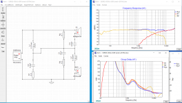
Do you think that is possible? , I've designed something in xsim, for a speaker that I'am building and it seems that it has a good coherence, what do you think?
I've searched around for a series crossover designed with time&phase coherence, and I wasn't able to find some article about it.
Do you think that is possible? , I've designed something in xsim, for a speaker that I'am building and it seems that it has a good coherence, what do you think?
Attachments
Last edited:
What does the acoustic phase look like for the drivers? (original post displays group delay)
I don't use XSim, but here's a video that shows how to display acoustic phase on the spl response graph. (acoustic phase topic begins at about 6:35 into the video)
YouTube
Look for good phase tracking of the drivers throughout the crossover region. For example, with the summed spl response that is shown in the original post, phase for woofer and tweeter should track well from 2 kHz to 7 kHz, or even beyond the bandwidth of interest -- in both directions.
Also, what about the impedance? Especially watch for the minimum that can be tolerated. With the right combination of drivers and circuit components, series crossovers can yield fairly flat impedance loads, which can be desirable for power considerations.
Last edited:

Without taking anything at all away from them, I would suggest they are better described as electrical topologies rather than designs, as I've yet to see anything there resembling a real driver's impedance or frequency response, both of which, to say nothing of acoustic offsets, have an enormous impact on results and what needs to be done electrically.
A lot of that is based on textbook formulae, and not actual measured systems. I have not seen that reverse-cascade method to an SXO before either. I may have to model with that style at some point...
Wolf
Wolf
And did it measure the way it was described when real, non-coincident drive units with varying impedance, frequency and phase angles were employed?
As noted, no reflection on the work put into a creative circuit topology, but it's no different from any other textbook electrical filter created using ideal electrical resistive loads without reference to the actual on-baffle electrical and acoustic responses: it won't (can't) work as described unless you put a great deal of effort into selecting the drive units, crossover frequencies and baffle design, none of which appears to be even mentioned on the page in question.
As noted, no reflection on the work put into a creative circuit topology, but it's no different from any other textbook electrical filter created using ideal electrical resistive loads without reference to the actual on-baffle electrical and acoustic responses: it won't (can't) work as described unless you put a great deal of effort into selecting the drive units, crossover frequencies and baffle design, none of which appears to be even mentioned on the page in question.
Broskie doesn't take into account that most practical xovers will be using different orders of slope on each of the drivers. Series xovers are an interesting mind game, but for most practical purposes, parallel will get you there much faster.
I've played with both SXO/PXO a lot, and it's not just cut and dried that one is easier/faster to get to the best or optimal result. In fact, some times the SXO can get there with fewer parts, less copper involved, and therefore cheaper system cost. Being they work differently means they apply differently, but not one better than the other.
Later,
Wolf
Later,
Wolf
Looks similar to an AR series xo. If C1/R3 is a zobel, the C1 should connect after L2 (i.e. across the woofer terminals).
More specifically, drivers may already have a 1st or 2nd order acoustical slope in their frequency response, so you may only need for instance a 3rd order electrical to hit a 4th order acoustical target.Broskie doesn't take into account that most practical xovers will be using different orders of slope on each of the drivers.
Agreed. SXO is more efficient in number of components, but a lot more difficult to design as drivers and components participate in multiple filters at once. PXO is much easier to design as each driver/filter acts completely independently but you double up on components performing similar tasks.I've played with both SXO/PXO a lot, and it's not just cut and dried that one is easier/faster to get to the best or optimal result. In fact, some times the SXO can get there with fewer parts, less copper involved, and therefore cheaper system cost. Being they work differently means they apply differently, but not one better than the other.
Last edited:
And did it measure the way it was described when real, non-coincident drive units with varying impedance, frequency and phase angles were employed?
As noted, no reflection on the work put into a creative circuit topology, but it's no different from any other textbook electrical filter created using ideal electrical resistive loads without reference to the actual on-baffle electrical and acoustic responses: it won't (can't) work as described unless you put a great deal of effort into selecting the drive units, crossover frequencies and baffle design, none of which appears to be even mentioned on the page in question.
I used an active crossover for picking my crossover points and slopes. Changing to the Broskie crossover while using 2 of the previous 6 amplifiers the FR plot barely changed compared to what I had from the active system.
As I don't use baffles I didn't have issues with these. I physically time align my horns. A slight adjustment was needed after switching to the speaker level crossover.
Impedance is tricky. The impedance plot of the whole is less flat than the plots of the single drivers. With the Broskie crossover Z in the mid region is lower than Z of the driver by itself.
Broskies writings are on the theoretcical side. Thought experiments if you will. It is what it is and in that domain quite interesting and worth reading.
And series crossovers are not the nightmare as they are portrayed by some. They are not harder to do than parallel crossovers. While playing with filters with the DSP I ended up liking 1st order best in that specific installment. Doing a 1st order parallel just didn't make sense.
I am only posting so i receive emails of this threats progress.
It appears I built a speaker with John Broskie's 4-way series shunt crossover, and made it symmetrical. I made it symmetrical because I have a dual differential (balanced) amplifier.
It is absolutely amazing. It was brutally expensive. It was worth it.
How do I find Mr. Broskie?
It appears I built a speaker with John Broskie's 4-way series shunt crossover, and made it symmetrical. I made it symmetrical because I have a dual differential (balanced) amplifier.
It is absolutely amazing. It was brutally expensive. It was worth it.
How do I find Mr. Broskie?
The OP may want to read Jeff Bagby's write up on the Tributes with it's series xo.
http://meniscus.lightningbasehosted.com/wp-content/uploads/2015/11/Tributes-Write-Up.pdf
Oddly enough, running the OP drivers with this xo in SCD is not too far off Jeff's results. The only issue could be the XT25TG likes to have it's Fs well down or it can sound harsh.
http://meniscus.lightningbasehosted.com/wp-content/uploads/2015/11/Tributes-Write-Up.pdf
Oddly enough, running the OP drivers with this xo in SCD is not too far off Jeff's results. The only issue could be the XT25TG likes to have it's Fs well down or it can sound harsh.
rabbitz, correct me if i'm wrong, he took the tributes to a number of competitions/shoot outs, and always won.
I don't know about 'always' but he won a few IIRC with those. Which is the point. There is nothing wrong with series filters (other than them being somewhat harder to design than parallel given the interactions with the circuit as a whole), and as noted above, on occasion they allow you to hit desired results with fewer components. However, astoundingly enough, they are not exempt from the laws of nature and have to be designed for a given set of drive units, with given frequency / impedance responses on a given baffle (or horn). These do not magically vanish simply by virtue of using a series crossover.
- Home
- Loudspeakers
- Multi-Way
- Time & Phase Coherence in series crossover