Hello,
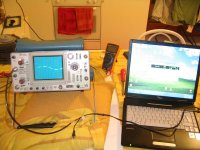
i just got a Tek 475A on ebay.
Personally it's been a veeery long time since last time that i have used an analogic scope.
There are a lot of regulations and triggerings that i don't know if i'm doing 'em right or not.
I have tried to hook the probe up to the test calibration outlet and check for the 300KHz square wave.
The wave on the crt can be triggered but it's spiky.
I also have tried to tap and touch the probe with my fingers to generate a 50Hz wave.
On the screen i'm only able to display the positive wave and part of the negative but not all.
I have tried to play around with regulations but didn't change a lot the final result.
I don't know if this i a problem of my scope or not.
Thereby i purchased on internet the service manual to see if i could check the functionalities along with it.
It looks very difficolt to me but, most of all, all the checks require equipments that i don't obviously have.
One of the tool on the list, that seems to be very usefull, is a time mark generator with marker outputs from 2ns up to 0.5s.
I don't know if i could easily build this or not and in case if it 's really necessary.
I guess that only few tests are needed to check the basic functionalities of the scope.
Since i still don't have a real signal generator i am thinking of using a pc-based wave gen for the firsts test on the scope.
I don't know if this is a low noise gen and can be fit the purpose.
What would be a minimum equipment to service such a scope?
Could i go with a
- fluke multimeter
- PC-based wave genrator
- (possibilty) time mark generator?
- Autotransformer (Variac?!)
- 10X probe
If anybody would be willing to help me with the troubleshooting i would really appreciate it and i'm here ready to follow instructions......also because....if the scope is defective.....i would like to return it!
Thanks a lot for your kind support.
one thing that happened when i hooked the scope to the power inlet.... i don't know if this thing can be usefull to understand the troubleshooting.... is that since here in italy the voltage system is 220-240V i have moved the black panel switch to the high position but havent't moved another switch placed on the side of the scope.
The result is that when i turned it on the black fuse blew up.
Replacing the fuse the scope worked.
I don't kow if this could have caused this thing
The result is that when i turned it on the black fuse blew up.
Replacing the fuse the scope worked.
I don't kow if this could have caused this thing
Yes, plugging into 220VAC when set to 120VAC is a very bad thing, and probably damaged something in the power supply. The first step in troubleshooting scopes is to check all the power supply voltages per the manual. As for the time mark generator, all you need is a signal generator, and the sound card will be fine for now. I use a regular signal generator and a frequency counter for accuracy, but that's way better than needed. One thing I find useful for troubleshooting scopes is... another scope!
the first thing i'll do is cheking the power supply accordingly with the service manal.
But i don't know exactly how a scope is made, of course, but i don't understand why i i don't completely see the 50Hz wave form inducted with the fingers on the probe....i mean...if there is a problem on the power supply.....i shouldn't be able to display anything.... well...maybe i'm saying some incorrectness...
As soon as i'm done with work i'll take a pic of the wave form and post it.
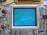
this is a picture of the scoper awhile trying to triggering a 10Hz wave and up till...about....400Hz the wave form is that fragmented....i don't know the reason..
is that a problem of the scope or some regulation that i'm missing
When i set the time base at x-y pposition i get the point on the screen.
When ch B is set and use the up down trigger of the ch A i move the point up and dow whilst using the up down trigger of the ch B i move the point left and right....
Buuutt.....when ch A is selected and i move the up-dw trigger on the chA, the cursor goes in diagonallllll.......and if i touch the up-dw trigger on the ch B nothig happens....
Please heelppp .... do i need to fix this scope and/or return it??
I have cheked the power supply value inside and there are all correct....i'm scared to put the scope apart since i think this type of work should be done from somebody with a certain experience on oscilloscopes repairing's field...anyway...not me.....i could try....but that's the only scoope i have gotten now 🙂 ....
Attachments
Hi Stefano- There could be something wrong, but I'm not sure. The display looked "chopped", which is how the scope displays two channels. See if you select only channel A if the trace goes solid. X-Y is used for Lissajous patterns, and without two signals, you'll get a line or spot. Be careful to keep the intensity way down or you'll burn the spot right into the phosphors of the tube. In general, if you see any blooming of the trace or spot under any conditions, turn the intensity down immediately.
ok, if i see some blooming i'll turn the intensity down.
In this case the illumination was normal.
You only see that because i used the flash on my camera.
The CRT works allright, i guess.
There are not missing/uncovered spots.
When i reach up to a certain frequency everything works out fine.
I can trigger whatever signal i want, at least until the upper extent of my sound card.
If i go down to 500-400Hz and lower, indeed, i get that not-continuos wave that i have posted here yesterday.
Yes, chanell A is solid selected (were you referring at x-y position where cursor on chanell A goes in diagonal?)
In this case, Could it be a problem with switchs!?? stucked....or whatever....a regulation that i'm missing on the scope?
Going back to the choked wave, with no signal at the input and start ing from the x-y position with the little point, by increasing the time division base the little point starts to move from the left to to right.
At a certaint point, though, i see a dash line....but increasing the time base a step or two further more, i finally obtain a solid line.
I don't have clue!!
Could it be some problems with the time base?
In this case can i, my self, having the ervice manual, do somrhitng for it?
Could it be some of the regulation on the scope that i'm missing?
My only 2 cents are trying to understand how to chatch low freq signal with a crt, when time div is at its first step, you can still see the cursor moving along the wave and therefore...how can you see a solid, for instance, sine wave?
I can conversely imagine that the solid line is displayed when the speed of the sweep if enough fast to give to our eye/breain the impression of a steady line.
I don't know....
really Hope to fix this issue...
scope problems
I have a Tek 465. The calibration lug outputs 1khz at 300 mv. This generates a very crisp square wave. Based upon your various explanations it sounds like you lost one side of the differential amplifier for channel A. There is a really nice description of a scope in the back of the Art of Electronics book. I would also try various probes to make sure that is not part of the problem. I have a crude signal generator made from an Intersil 8038 I think. I have a multi-turn pot for frequency adjustment and 3 ranges of frequencies. You can build this for almost nothing and it is amazing what you can do with just a signal generator and a (working) scope. An even simpler test is to connect the scope to a low voltage AC source like a 6 volt transformer. You should see a nice sine wave at the appropriate frequency. Good Luck,
Don
yes...that is the problem....if i would try to measure a 50-60Hz frequency, like for instance that at the output of the transformer...i would see a chopped wave....but if i would rise the frequency that problem would disappear.
It is not a problem of the probe, cause i connect the output of the sound card with a normal jack and i go directly to the input of the scope through a BNC connector.
It is not a problem of the probe, cause i connect the output of the sound card with a normal jack and i go directly to the input of the scope through a BNC connector.
sorry.... did you make your own signal generator?
What is the minimum step of frequency variation? What is the bandwith of your signal gen? can you get up to some Mhz?
if you made it by yourselfs, may you share the schematic with me?
What is the minimum step of frequency variation? What is the bandwith of your signal gen? can you get up to some Mhz?
if you made it by yourselfs, may you share the schematic with me?
Scope problems
Yes, based upon the Intersil 8038, which was available from Digi-Key last time I checked. Here is a link to this part at their site. http://www.intersil.com/data/an/an013.pdf I did not worry about precision, I only wanted a variable frequency source to verify that an analog circuit was working and what different frequencies do to the circuit. I have read from Nelsons accounts about using square waves for testing. This chip outputs square waves, triangle and sine waves. I don't know what the maximum range is but the spec sheet should say. I only concerned myself with audio range. I used to be really good with a scope when I was a disk drive specialist, but have forgotten some of my tricks! With digital work I was concerned with timing issues and rising and falling edges rather than levels in most cases. The scope is so useful for finding noise such as RF riding on a signal. It appears as fuzz until you speed up the scope and then you can see the actual problem usually.
Don
thanks for pointing that out.
For precision i meant low noise.
A low noise source will also allow you to verify that low floor noise is not introduced from your amp o pre.
Anyways i would like to build a low noise signal generator for testing purposes.
Righ now i'm using the output of my sund card....but i feel like it is a little noisy....but that's ok for right now.
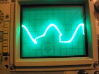
and this is a 40Hz wave with an high illumination (turned it up for few seconds) to show what there is behind the appereantly missing spot......this huuge distortion.
Anybody's good advice are obviously welcome.
(forgot to say that same thing happens on CH. A and CH. B )
Anybody's good advice are obviously welcome.
(forgot to say that same thing happens on CH. A and CH. B )
Attachments
- Status
- Not open for further replies.
- Home
- Amplifiers
- Pass Labs
- time mark generator and Tektronix 475A Service-Calibration