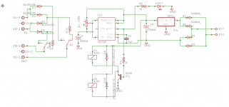
A while ago I found on the internet this circuit "Time Delay" that can be used for slow charging a capacitor bank. He has worked perfectly since. I drew the layout pcb and I will try to find it for upload. Just to share this project. You can adjust R1 (trimmer) to get from some milliseconds to hours for time delay.
Attachments
or just do as the Power Thermistor Manufacturers describe.
Stick an NTC in the secondary circuit.
Stick an NTC in the secondary circuit.
Yes, you are right. But there are two points to be considered: it's better bypass the thermistor after it did the job; second, it's to dificult to find a thermistor in some countries, as in my contry, with a complete specification. So, you need to import them and is usual take a long time to get them.
I agree on a bypass. One should strive to reduce the source impedance after the charging is completed.
That might not be as important when an rCRC PSU is being built.
That might not be as important when an rCRC PSU is being built.
A while ago I found on the internet this circuit "Time Delay" that can be used for slow charging a capacitor bank. He has worked perfectly since. I drew the layout pcb and I will try to find it for upload. Just to share this project. You can adjust R1 (trimmer) to get from some milliseconds to hours for time delay.
Did you ever find your pcb layout? I would really like to see it.
Also, what size of transformer are you using to power the timer circuit? I figure 12VA for a 9 VAC transformer powering two 120 ohm relay coils in parallel ought to be fine. But, it gets very hot.....
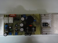
I used a protoboard. Tomorrow night I will sending a picture of it, to assist in layout. I'll try to find the layout that I made with eagle.
Also, what size of transformer are you using to power the timer circuit? I figure 12VA for a 9 VAC transformer powering two 120 ohm relay coils in parallel ought to be fine. But, it gets very hot.....
I will check and return you back tomorrow. The transformer is working cool ...
120ohm 12V relays will draw ~100mAdc............ I figure 12VA for a 9 VAC transformer powering two 120 ohm relay coils in parallel ought to be fine. But, it gets very hot.....
Two relays will draw ~200mAdc.
If this is the only load on the transformer then a 400mAac transformer will be at full capacity when feeding a capacitor input filter.
400mAac 9Vac transformer equates to 3.6VA.
I usually suggest doubling the minimum transformer rating for continuous currents. This ensures cool and reliable operation.
12VA should not run hot.
Does it run cold, or warm, or hot with no output connected?
 Thanks AndrewT, I had wired it incorrectly.
 12VA ought to be just fine.....
BTW appneto, would'nt the power supply capacitor be better on the input side of the 7812?
The circuit works, I did not use the 7812, and used a 100uF cap instead of 1000uF. It also simulates well with a mockup of a transformer driving a 60 ohm resistive load (that would be 2 120 ohm relay coils in parallel).
Using a 12VA transformer, rated at 9 VAC, the voltage drops to 9.4 VCD across the load resistor , which ought to be enough to operate the relay that activates at 9 VDC.
Using a 2200u cap results in 11.5 VDC across the load resistor, which will definitely operate the relay. The 9.4 and 11.5 numbers are direct measurement, not simulation.
Last edited:
The 9.4V and 11.5V are not constant DC voltages.
They are a very high ripple voltage imposed on a DC voltage.
The DMM measures the AVERAGE voltage of the rippled DC.
9.4V average from a 9Vac transformer winding indicates a very high ripple. Some DMM set to AC can safely measure the ripple separate from the DC. Can your DMM do this?
The ripple peak to peak is very roughly 3times the DMM Vac reading.
eg. your 9.4Vdc may read 3Vac. This would indicate ~9Vpp of ripple.
Half that ripple is above the average of 9.4V, i.e. 13.9Vpk
The lower half of the ripple will be below the average of 9.4V, i.e. 4.9Vmin.
The 9.4V is actually 4.9Vmin to 13.9Vpk when you measure the values given as an example.
You can "see" this if you use a scope to look at the wave shape of the DC voltage.
Compare the Vac for the 2200uF to the Vac with the 100uF
There is a very general rule to use ~2000uF (2mF) for each ampere of output DC current.
For 400mAdc that would indicate ~800uF. Try 1mF
Last edited:
Do not operate a relay at a voltage where it only just allows it to close/changeover.
this action does not wipe the contacts adequately and leads to bad contact.
You can use the full rated voltage to get good wiping and then reduce the operating current to a lower level to hold a pair of clean contacts together.
I do this by using a current saving circuit.
I typically use 15V from a regulator feeding a 12V relay that fires/triggers the relay with a capacitor charged to ~14Vdc to 15Vdc and then reduces the holding voltage to ~9Vdc.
This runs the relay coil cool and draws less current from the PSU.
Thanks AndrewT, I'm away at this point, but will check with the scope on return. It will be interesting to see how close the LTspice simulation is to measured values.
AndrewT,
I'm a bit confused about the operation of the relay between contact closure and release voltages. The 12V relay closes at 9 VDC, but releases at under 2 VDC. Nothing uncertain about that.
You seem to be saying that there is a measurable change in contact resistance once the control voltage drops below 9 VDC yet remains above the release voltage.
I've yet to order my relays, having just verified the operation of the 555 timer circuit, or I'd measure that myself using a benchtop function generator. I want to take it one step at a time, then when all parts are verified, focus solely on assembly.
Second question:
What do you use as ground for the relay circuit? Not the main audio ground I hope.
What do you use as ground for the relay circuit? Not the main audio ground I hope.
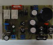
Sorry for late reply, due to family commitments. My intention was to create a universal board with VDA ranging from 12 to 18. For this reason I used CI 7812 . My transformer was 12VDA, 500ma and it worked fine. The layout shown in the picture below incorporates other functions (control bias and voltage regulator) for a tube amp. I will redraw the circuit for delay function to use it in multiple amp.
Attachments
The 7812 is easily bypassed if not desired. A simple jumper from input to output, and no connection to ground would do.
However, I suggest adding pads to connect optional terminals for use of external relays -- either quick-on tabs/keystone/PCB screw terminals. Anything actually.
However, I suggest adding pads to connect optional terminals for use of external relays -- either quick-on tabs/keystone/PCB screw terminals. Anything actually.
this one first.Second question:
What do you use as ground for the relay circuit? Not the main audio ground I hope.
The current to the relay driving circuit comes from a source. That current MUST return to the same source.
The two wires supplying and returning that relay current should be a close coupled twisted pair. It should be obvious where the Return needs to terminate.
Open up a BIG redundant relay.AndrewT,
I'm a bit confused about the operation of the relay between contact closure and release voltages. The 12V relay closes at 9 VDC, but releases at under 2 VDC. Nothing uncertain about that.
You seem to be saying that there is a measurable change in contact resistance once the control voltage drops below 9 VDC yet remains above the release voltage.
I've yet to order my relays, having just verified the operation of the 555 timer circuit, or I'd measure that myself using a benchtop function generator. I want to take it one step at a time, then when all parts are verified, focus solely on assembly.
Look at the way it operates. One contact is fixed to a rigid arm.
The other contact is fixed to a flexible arm.
The flexible arm "bends" as the contacts touch. one contact slides over the other contact. This is the "wiping" action that helps to keep the contacts clean and maintain a very long life.
The solenoid starts with a BIG gap to the armature, the iron part that moves and pulls the contact arm.
When the rated current is passed through the solenoid you will almost certainly see a gap between the armature and the solenoid pole.
as you reduce the coil current the small gap will increase, as you increase the coil current above rated you will see the gap decrease. The bending arm of the moving contact holds the armature away from the solenoid pole.
Severe over current may just about eliminate the gap. That is not good for quick release.
All of those details are repeated on the small and tiny audio level relays.
You need sufficient movement of the armature to "wipe" the contacts. The final position of the touching points will be between the first contact and the last contact of the wipe length. This is the part that has just been cleaned.
If you use a very low pull in current, then the wipe length will be short. the contact pressure will be low. The final contact point may be very near or on the start of the wipe length. This can lead to poor audio due to dirty contacts.
Very low contact pressure can lead to contact bounce in the presence of mechanical vibration. I have found success with operating current/voltage @ roughly half way between rated and release current/voltage.
But I generally use higher than that average to give a bit more safety margin. A 12V relay would probably drop out at ~3Vdc. Halfway between rated and drop out is 7.5Vdc. In the example earlier I suggested 9Vdc, that is 1.5V above this average. And results in much cooler operation.
You could probably work with an operating voltage half way between lowest closing voltage and highest opening voltage.
I have not tried to work long term with this low a contact pressure.
I know it works in the short term on the bench and during short term testing.
Last edited:
- Status
- Not open for further replies.
- Home
- Amplifiers
- Power Supplies
- Time delay to slowly charge a capacitor bank