Hello.
I'm currently designing my own linear power supply.
Everything seems going well, but there is one thing I concern about.
Can I make the center tap of transformer with tying pins of fall apart to each side away?
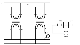
The datasheet of transformer I used tells that I have to tie 9 and 10 pins to get series output, but unfortunately the PC board layout currently designing by me may not allow me to do that by some reasons, so I decided to tie 7 and 12 pins to make the center tap(GND).

Would it cause a problem or perfectly trustable?
Here's the datasheet of Transformer : https://catalog.triadmagnetics.com/Asset/VPP36-1560.pdf
I'll look forward for your opinion.
Thanks for reading.
I'm currently designing my own linear power supply.
Everything seems going well, but there is one thing I concern about.
Can I make the center tap of transformer with tying pins of fall apart to each side away?
The datasheet of transformer I used tells that I have to tie 9 and 10 pins to get series output, but unfortunately the PC board layout currently designing by me may not allow me to do that by some reasons, so I decided to tie 7 and 12 pins to make the center tap(GND).
Would it cause a problem or perfectly trustable?
Here's the datasheet of Transformer : https://catalog.triadmagnetics.com/Asset/VPP36-1560.pdf
I'll look forward for your opinion.
Thanks for reading.
Your connection will not give you the rated output voltage of the transformer.
As a side note: Please use caution when dealing with mains level voltages and never proceed in the face of uncertainty. Mains voltage as unforgiving.
Best Regards,
Brannon
As a side note: Please use caution when dealing with mains level voltages and never proceed in the face of uncertainty. Mains voltage as unforgiving.
Best Regards,
Brannon


That is not what the datasheet is saying…
This is a PC mount transformer, not leaded, so the connections are “pins”.
The datasheet is expecting you to use the secondaries either in strict parallel or in series.
For series, which will give 36VAC, you need to take output from pin7 and pin12. You must connect, “jumper”, pin9 to pin10.
For parallel, to get 18VAC, you still take output from pin7 and pin12. You connect (jumper) pin7 to pin10, and pin9 to pin12.
Thank you for all.
I will follow the advice of 6L6, tie 9+10 pins.
(I forgot to draw fuse at mains supply, which I've already take it)
I will follow the advice of 6L6, tie 9+10 pins.
(I forgot to draw fuse at mains supply, which I've already take it)
And one more may sounds like dumb question...
Would it be safe if I connect the above transformer with metal screws which connected to chassis? (metal chassis are connected to ground)
I've heard that grounding double-insulated device is illegal. And I wonder how can I mount that transformer using screws properly...
Would it be safe if I connect the above transformer with metal screws which connected to chassis? (metal chassis are connected to ground)
I've heard that grounding double-insulated device is illegal. And I wonder how can I mount that transformer using screws properly...
I see no reason why you can't tie 7-12 together and take your output from 9 and 10. Your two drawings in post 1 will work identically.
All you are doing is swapping relative positions of each winding. The transformer could care less "who is on the right" and "who is on the left"
All you are doing is swapping relative positions of each winding. The transformer could care less "who is on the right" and "who is on the left"
True, but that does ignore the physical construction of the transformer. The manufacturer recommended connection keeps the pins with the highest voltage swing furthest away from each other - this makes creepage and clearance requirements on the PCB easy to achieve. On a very low voltage output, you are may well be safe with the alternate wiring but why ignore the manufacturer's recommendation?
Actually, it is the physical construction of the transformer that tells us we CAN do this confidently. Low voltage windings with split bobbin construction. These are not designed for low capacitance via winding connection - the bobbins do that for them. Voltage swing and creepage concerns for a 36V output? Not at all.
The manufacturer provides a recommendation to make the connections idiot-proof. If they provided all the possibilities of how to connect the windings, it would add confusion. Better to keep it simple. However, the OP asked a question, the proper answer is "of course you can". Prior posts stated "you can't" which is not true.
The manufacturer provides a recommendation to make the connections idiot-proof. If they provided all the possibilities of how to connect the windings, it would add confusion. Better to keep it simple. However, the OP asked a question, the proper answer is "of course you can". Prior posts stated "you can't" which is not true.
If that was a 360 volt (or 240V) secondary, you would want to do it the way the manufacturer suggested. At 36V it probably doesn’t matter. They also don’t recommend using the windings completely separately, but on these low voltage ones I have with no trouble. As long as the voltage differential doesn’t get stupid. Never needed to elevate a tube heater more than 68 volts either, and most of the time less. I wouldn’t use one side as a bucking winding for mains, or for the heater of a tube rectifier (up at B+). But doing things like making separate 12V and 5 V supplies, each with their own rectifier and regulator, no issue as long as both get their ground sides connected somewhere, locally.
Huge thanks to everyone for replying.
I sent an email to MFR asking about above discussion 2 weeks ago to make it clear, but sadly still they make no reply to me.
In this situation I would likely to scratch according to zigzagflux's suggestions.
I sent an email to MFR asking about above discussion 2 weeks ago to make it clear, but sadly still they make no reply to me.
In this situation I would likely to scratch according to zigzagflux's suggestions.
Yes, this is true, you can. The only electrical difference between the two configurations is the phase relationship between the primary and the seconday, which is not a concern for a power supply.However, the OP asked a question, the proper answer is "of course you can". Prior posts stated "you can't" which is not true
- Home
- Design & Build
- Electronic Design
- Tie the Transformer's CT as vise-versa