Dominique said:I'd rather think that the soldering was a bit harder to do.
He does have a point. The centre pad on QFNs is usually there to conduct heat away from the chip. The intention is that you tie it with vias to a ground plane, so that the plane can do the dissipation. If you can't do plated through vias though, it means the chip won't be able to dissipate nearly as much as it could on a proper board.
Having said that though, double sided plate through boards are cheap as chips to get made these days. I very rarely resort to making my own boards.
Regards,
Suzy
Ok, I'll look for more info on that center hole method, I've seen that described somewhere with images.
You're right, the heat conduction won't be that great with my heat-conductive glue, but for something less power demanding, it could work out, couldn't it? (Sorry, I think that was what you said, but I'm not sure if I understood you correctly).
Cheers,
Dominique
You're right, the heat conduction won't be that great with my heat-conductive glue, but for something less power demanding, it could work out, couldn't it? (Sorry, I think that was what you said, but I'm not sure if I understood you correctly).
Cheers,
Dominique
Here's a thought. For QFNs on home made boards (and other packages with a centre pad) you could always simply solder a copper slug to the pad, and pass that through a hole in your PCB to a heatsink on the other side...
Regards,
Suzy
Regards,
Suzy
suzyj said:
I'd wager quite a decent amount that you wouldn't be able to hear kilowatts of sound energy at 300KHz.
Why do you say that?
I just mentioned 100kHz, 'cause the device is a high speed device and the graphs in the datasheet don't go below 100kHz.
So I can only guess, but the curve doesn't look that promising for lower frequencies.
It's the overall level of the harmonics that count, at frequencies that people's ears are actually sensitive to. Except of course with mediocre amplifiers with >1% THD, where higher order harmonics really are audible, and sound bad.
That's the opposite of what everyone in acoustics and music theory states. You're able to hear higher order distortions much more than lower order, and odd order much more than even order harmonics. Off course, the 5th order of 5kHz isn't that much interesting me either 🙂
I just recently saw a graph on the subject and 5th order harmonic was stated as audible (for normal people) at well, sth. like -93dB or so.
Cheers,
Dominique
PS. Here's the graph.
I don't claim I'll hear any distortions on that chip 🙂 , but if 3rd is above 2nd, I'd like to know where e.g. 5th is.
On most audio devices' harmonic distortion graphs I've rather seen higher figures for low order harmonics, diminishing with higher orders.
I mean, even while probably distortions won't be audible anyway, if I like them to be as far away from audibility as possible, then not in an absolute way, but adapted to our ears sensitiveness.
Attachments
suzyj said:Here's a thought. For QFNs on home made boards (and other packages with a centre pad) you could always simply solder a copper slug to the pad, and pass that through a hole in your PCB to a heatsink on the other side...
Yes, that sounds easy! Thanks for the hint!
Cheers,
Dominique
Dominique said:PS. Here's the graph.
I don't claim I'll hear any distortions on that chip 🙂 , but if 3rd is above 2nd, I'd like to know where e.g. 5th is.
On most audio devices' harmonic distortion graphs I've rather seen higher figures for low order harmonics, diminishing with higher orders.
I mean, even while probably distortions won't be audible anyway, if I like them to be as far away from audibility as possible, then not in an absolute way, but adapted to our ears sensitiveness.
I just had a look at the data for the chip.
The relative level of distortion at a given frequency follows the open-gain. Indeed you can see this from the slope of the distortion levels on the graph, at ~20dB/decade. An amplifier like this one with a 3rd order harmonic down 90dB at 100KHz, is likely to be -110 at 10KHz, etc...
That's pretty impressive.
Cheers,
Suzy
Well, if I look on the graph I posted above (with a load of 25 Ohm), I rather see the 3rd down "only" 🙂 by sth. like -100dB. at 1kHz.
Ok, I see, I'll have to make a PCB for a headphone amp and measure higher order harmonics by myself...
Ok, I see, I'll have to make a PCB for a headphone amp and measure higher order harmonics by myself...
One instresing application with couple of TPA6120...
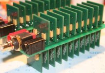
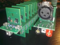
I have built a bridge tied outout amplifire (~25W@8Ohm) with 20pcs paralell connected TPA6120 few month ago, because I found the TPA6120 as great device to drive my fast Triange speakers.
I have hade opportunity to measure distortion with Rohde Schwarz UPL Audio analyzer. Unfortunetly measurement results were not well documented, but the next numbers are still crystal clear for me:
2nd harmonic was always below -120dB and 3rd harmonic was the bigest one with -96dB up to tested 20kHz freq.
Testcondition:
Voltage output: ~12Veff
Load: 3pcs 22Ohm parallel = 7,3Ohm.
PowerSupply: 2x 12V/7Ah Lead Acid battery
Attachments
mzperx said:
I have built a bridge tied outout amplifire (~25W@8Ohm) with 20pcs parallel connected TPA6120
----
PowerSupply: 2x 12V/7Ah Lead Acid battery
Nordic said:Pretty sweet MZ. Wanna share a schematic?
Same idea done before? Yes. Probably with same very good results!
We have this wellknown project at
http://www.headwize.com/projects/
six years ago, 2006, by Jan Meier
2 x 44 (=88 opamps) single channel operational amplifiers
working together!
An externally hosted image should be here but it was not working when we last tested it.
The design
This all-opamp power amplifier has 44 output opamps per channel!
.....
Power handling is one of the reasons I decided to use the LM6171
instead of its dual version LM6172.
Note that 2 x 44 amps have quite a large total body surface
so any heat is easily transferred to the air.
http://www.headwize.com/projects/meier3_prj.htm
.
christmas
lineup
Lineup Audio Lab
http://lineup.awardspace.com/
mzperx said:
Lineup, thanks for a link. Unfortunately I didn't see the mentioned version earliear.
To compare my amp to Meier's amp there are many significant differences...
I think one major difference is
TPA6120 has got more Output Current Than LM6171.
About max power these chips can dissipate, I do not know.
But my guess is your choice, TPA6120, all in all,
is more suitable than LM6171 for Power Amplifier.
You wouldn't need as many as 44 to get ~10 Watt RMS output.
Thanks for the Attached ZIP file, mzperx.
I will take a look.
christmas
lineup
Hi,
I`m looking to make a portable amplifier with TPA6130A2 for my 50 ohms headphones, but I don`t have any ideea how to use I2C interface for volume control. I can waive to the I2C interface and control the volume from phone or player, but the amp will work?
Thanks,
Paul.
I`m looking to make a portable amplifier with TPA6130A2 for my 50 ohms headphones, but I don`t have any ideea how to use I2C interface for volume control. I can waive to the I2C interface and control the volume from phone or player, but the amp will work?
Thanks,
Paul.
Please find the attached schematics.
Lineup, thanks for a link. Unfortunately I didn't see the mentioned version earliear.
To compare my amp to Meier's amp there are many significant differences...
Why does the Schematic show two 10ohm resistor in parallel at each TPA6120 output? (5 Ohms by output)
The TPA6120 Datasheet suggest a value >= 10 Ohms for each TPA6120 output.
I would like to try two TPA6120 in parallel!!!
Regards.
Alfredo Mendiola Loyola
Just because of SMD 0805 resistor's power and current handling capability.Why does the Schematic show two 10ohm resistor in parallel at each TPA6120 output? (5 Ohms by output)
In the final version 2ohm resistors are applied in order to ensure lower output impedance. The amp keeps stable even with this lower value.
Attachments
Just because of SMD 0805 resistor's power and current handling capability.
In the final version 2ohm resistors are applied in order to ensure lower output impedance. The amp keeps stable even with this lower value.
Can I use A 2 ohm or 4.9 ohm resistor at the TPA6120A output if it is not connected in parallel with another TPA6120A output ?
Regards.
Alfredo Mendiola Loyola
Lima, Peru
Paralleling of the modules can mitigate the effective capacitive loading of a single module so the series resister is less critical in that case.Can I use A 2 ohm or 4.9 ohm resistor at the TPA6120A output if it is not connected in parallel with another TPA6120A output ?
If you have moderate capacitive load and not too low Rf than ~5ohm can work fine.
the resistors can be sized just for current sharing, have their output Z effect reduced by global feedback
unless running out of V swing I would keep the sharing resistors above a few Ohms - the parallel amp outputs also see each other's complex output Z
and you may want them to survive large signal oscillation where one output isn't tracking the other and the currents between the two can become large
outside of the feedback loop output load isolation can be had with series L, air coil or lossy ferrite with little or no audio frequency compromise
http://www.diyaudio.com/forums/head...opa2227-ne5532-composite-headphone-amp-2.html
remember when using CFA op amps as current buffers - if you use CFA op amps in unity gain you still have to have the correct value Rf from output to -input
many times you may even want to make it larger the datasheet value to "overcompensate"
and be paranoid about stray C to the CFA -input - look at the eval layout - even cuts a window in the gnd plane on the far side of the board under the -input, feedback R pad, trace
Last edited:
the resistors can be sized just for current sharing, have their output Z effect reduced by global feedback
unless running out of V swing I would keep the sharing resistors above a few Ohms - the parallel amp outputs also see each other's complex output Z
and you may want them to survive large signal oscillation where one output isn't tracking the other and the currents between the two can become large
outside of the feedback loop output load isolation can be had with series L, air coil or lossy ferrite with little or no audio frequency compromise
http://www.diyaudio.com/forums/head...opa2227-ne5532-composite-headphone-amp-2.html
remember when using CFA op amps as current buffers - if you use CFA op amps in unity gain you still have to have the correct value Rf from output to -input
many times you may even want to make it larger the datasheet value to "overcompensate"
and be paranoid about stray C to the CFA -input - look at the eval layout - even cuts a window in the gnd plane on the far side of the board under the -input, feedback R pad, trace
Can I use a composite amp using an opa2134 and a tpa6120 inside the OPa2134 feedback loop?
If I put the TPA6120+the 10 ohm output resistor inside the OPA2134 feedback loop, the 10hom output impedance of the (TPA6120+10 Ohm) will be reduced?
Regards
Alfredo Mendiola Loyola
Lima, Peru
should work, the 10 Ohms (outside the TPA local loop) would isolate the TPA output from load C effects at >10s of MHz
but 10 Ohms is lower than the OPA134 open loop output Z so wouldn't make its stability any worse even though the 10 Ohm is inside its feedback
the simplest formula for stability is to make the local gain of the TPA less than the outer loop gain so that the OPA134 is operating above unity loop gain
but 10 Ohms is lower than the OPA134 open loop output Z so wouldn't make its stability any worse even though the 10 Ohm is inside its feedback
the simplest formula for stability is to make the local gain of the TPA less than the outer loop gain so that the OPA134 is operating above unity loop gain
- Status
- Not open for further replies.
- Home
- Amplifiers
- Headphone Systems
- TI headphone amp with interesting possibilities