Isn't the heater supply a bit low?
How do you turn it off? hit K1? A more sure way would be N.O. momentary contacts shunting the tube or N.C. contacts in series.
Otherwise I suppose it should work.. have fun with the glow 😀
Tim
How do you turn it off? hit K1? A more sure way would be N.O. momentary contacts shunting the tube or N.C. contacts in series.
Otherwise I suppose it should work.. have fun with the glow 😀
Tim
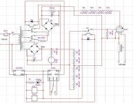
Thanks Tim, 2.5v @21 Amps is correct I belive. Right now it's drawn so that when Reset is slected on the 555 timer, it sends the output low to kick out K1. The timer is there to allow the filament to heat up before the anode supply kicks on. I've read that thyratrons aren't too forgiving about a hot anode with a cold cathode. The drawback is that the timer has to recycle before anode voltage is applied again. Thanks!
Ah, I see now. Was too tired, thought the resistor K1 switched in was for soft start or something. 😉
Hmm, I presume you want this thing to operate, i.e. switch on and off? Then shouldn't the grid be switchable rather than always on? Or are you going to leave it always-on and just toggle plate voltage?
I thought you had a giant 6.3V 20-30A unit..?
Tim
Hmm, I presume you want this thing to operate, i.e. switch on and off? Then shouldn't the grid be switchable rather than always on? Or are you going to leave it always-on and just toggle plate voltage?
I thought you had a giant 6.3V 20-30A unit..?
Tim
Heh, yeah I kinda forgot to draw a momentary switch in series with the coil of k2 for starting. The resistor on k1 acts as a bit of a load for that winding of the transformer. Since it's on whether the anode is hot or not, I didn't want those leads to be hanging out looking for ground.  I do have another one, a JAN 5948 that IS a monster. That's next. 🙂 Thanks!
-Ricky
I do have another one, a JAN 5948 that IS a monster. That's next. 🙂 Thanks!-Ricky
- Reverse the diodes on the relays, and the LED 😛
- What's the choke in the thy's heater for?
That's about all I can think of, looks fine. Of course I could make pedantic remarks like, "you sure you can find a 2kV electrolytic?" 😉 (I'm going to guess those are either removed from microwaves (..PT(s) too?..) or a big stack of 'lytics.)
Tim
- What's the choke in the thy's heater for?
That's about all I can think of, looks fine. Of course I could make pedantic remarks like, "you sure you can find a 2kV electrolytic?" 😉 (I'm going to guess those are either removed from microwaves (..PT(s) too?..) or a big stack of 'lytics.)
Tim
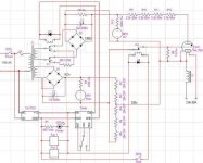
Heh, right those do need to be reversed. 😱
I read that these can put a spike down the filament supply when the tubes switches because the filament is tied to the cathode. It was suggested that a choke capable of handling the current be used to absorb such spikes. Is that an unnecessary component? Would such spikes only occur under abnormal conditions? The caps I bought from Surplus Sales of Nebraska. Big oil filled AC caps, uprated for DC use. I've got most of the parts, but I wanted to double check what's on paper before I finish building it. Thanks!
-Ricky
Nice caps 😀 I somehow doubt it'll do anything odd switching a tiny resistive load, but if it isn't wasting money I suppose it couldn't hurt... always going to kill voltage though, 20A is a lot for a choke, especially with 2.5V across the whole thing. Your filament tranny good for that?
Tim
Tim
It should be, the choke is rated for 30A and the filament supply is a lab 0-10v 25A supply. Because the supply voltage will be regulated, I figured it would be a good idea to havea choke in there. In testing, the choke only dropped about 1 volt (it's a big sucker- low resistance) So the supply can easily make up for that.
I got about 50 of those chokes from a theatrical dimmer rack I scrapped back in college. I have several 50A chokes for the 5948 as well. 😀 Thanks!
-Ricky
I got about 50 of those chokes from a theatrical dimmer rack I scrapped back in college. I have several 50A chokes for the 5948 as well. 😀 Thanks!
-Ricky
- Status
- Not open for further replies.
- Home
- Amplifiers
- Tubes / Valves
- Thyratron Circuit