Hi
I have this amp and I'm adjusting the bias for the two channels and have a few questions I'm hoping someone can answer for me. I bought the amp with a problematic channel but after looking at it I noticed one of the thermistors, RT3 was not in the heatsink. I put it back together and replaced both trimpots with 4 turn so I wouldn't have the sharp adjustment of the 1 turn. The amp voltages and currents all check out fine and I've spent some time trying to figure out the imbalance in temperature between the two channels and have some hypotheses but need to confirm some things first.
Thanks,
Kevin
I have this amp and I'm adjusting the bias for the two channels and have a few questions I'm hoping someone can answer for me. I bought the amp with a problematic channel but after looking at it I noticed one of the thermistors, RT3 was not in the heatsink. I put it back together and replaced both trimpots with 4 turn so I wouldn't have the sharp adjustment of the 1 turn. The amp voltages and currents all check out fine and I've spent some time trying to figure out the imbalance in temperature between the two channels and have some hypotheses but need to confirm some things first.
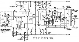
- Does anyone have the FEB parts list that shows component values?
- What is the "B" value of the 1K & 3K thermistors? 3800?
- Should 49C at the rear of the heatsink be the target for this amp as listed in the bias procedure?
Thanks,
Kevin
Last edited:
Thermistor manufacturer?
Looking for any input on the thermistors(RT1,RT3). I have confirmed the thermistor in this amp has a B=3500 which means by design the Opamp, U4, should turn on around 48-50C although the output is at 2 volts at 43C and is driving the second opto, U5. My guess is the actual thermistor used is more like a B=3700 or so. Can anyone tell me what the original manufacturer was for the thermistor in the "e series"? I have more measurements to take, difficult with the way the amp is built.
Thanks,
Kevin
Last edited:
Thanks Nelson. I have this amp idling with no load measuring about 42C at the recommended measurement site at the back of the amp after an hour, ambient is 25C in the room. The initial current I have increased to 1.5A from the recommended 1.2A start point. It seems to be working fine, however there does not seem to be a way to achieve the 49C target without getting very aggressive with the adjustment at U3. Both channels match now after I found an issue with a thermistor out of the hole! Should I pursue the higher idle temp? Thanks for your input.
Kevin
Kevin
Yes, if you run out of pot, try raising the value of R20 a bit.
I like to bias for 50 deg C on the top of the sinks for this amp.
I like to bias for 50 deg C on the top of the sinks for this amp.
Thanks again Nelson, 50C that's what I thought you'd say 🙂. My concern was increasing the initial current in each channel by too much in order to achieve 50C. I have plenty of pot left, I had installed a 4 turn pot so I have better control as well. R20 is 2.2K right now which is factory.
Kevin
Kevin
Well, starting with 3A across the .01ohm supply rail resistor I end up right at 50C, nice and toasty. Then minutes later, bam back down to 44C like clockwork. I notice the schematic calls out .23V across R29 which is a 392ohm resistor, using this value that voltage is closer to .27V. This means the thermistor with B=3500 crosses that threshold right around the 50C point when the opto U5 will kick in. The .23V, from a math standpoint would require a 330ohm resistor which would mean U5 wouldn't start to turn on until about 55C which would allow me to reach 50C without U4 driving U5 yet. I don't know what the value should be, just what's on the board but this makes sense to me. I'm chasing my tail increasing the bias current continually while U4 just turns on and further pulls down the bias. Am I missing something? I wish I knew if this value is correct for the R29.
Kevin
Kevin
I'm clueless 🙂
Pa is there , he chewed it eons ago ...... and I'm sleepy , so better to shut up than make some damage
.......
Pa is there , he chewed it eons ago ...... and I'm sleepy , so better to shut up than make some damage
.......
Thanks Zen, My inexperience working on Thresholds leads me to the analysis and I understand that I don't understand and I'm trying to understand.
Kevin
Kevin
I don't know what the value should be, just what's on the board but this makes sense to me. I'm chasing my tail increasing the bias current continually while U4 just turns on and further pulls down the bias.
It took me a little effort to look at this, but I believe your analysis is
correct. There's no reason why you shouldn't adjust the resistor to get
the trigger at a higher point. I would shoot for 60 deg. and see what
you get.
Frankly, I don't recall how we ended up with such a complicated circuit.
It took me a little effort to look at this, but I believe your analysis is
correct. There's no reason why you shouldn't adjust the resistor to get
the trigger at a higher point. I would shoot for 60 deg. and see what
you get.
Frankly, I don't recall how we ended up with such a complicated circuit.
Thanks so much Nelson for looking into this, I know you have many other fish to fry! At least I know I'm not totally nuts here. I goosed it up to 3.5A initial current per rail and sure enough, back down to 42C! Another 1.5A and I'm blowing line fuse. I will try 330 ohms on R29. That value, in this circuit, represents the corresponding temperature on the curve for the 1K@B=3500 at turn on which is about 57C give or take with offsets.
Kevin
weed was much better then

LOL, yeah you weren't as paranoid, change was inevitable(even with circuits)!
weed was much better then
ZM:
The evidence overwhelmingly indicates otherwise.
Regards,
Scott
Ok, FYI. Last night I pulled out my S450e manual that I forgot I had and noticed that the Opto used was the CNY17-3. Well apparently this "reissue" used a CNY17-4 which has a CTR(current transfer ratio) of almost 2X with 2ma applied to the emitter diode! So in a nutshell, I've got almost 2X the current,the original design had, flowing in the collector of U3/U5 which shunts the current around R22 which determines the bias voltage. All of the other components are unchanged so this means the bias will be lower by virtue of the higher "transfer ratio". I believe this is the real issue and I'm going to get some -3's and try it out. Also, I will have another glass of wine 🙂 I will let you know how this works.
Thanks,
Kevin
Thanks,
Kevin

- Home
- Amplifiers
- Pass Labs
- Threshold S350e "Reissue"