I'd like to try converting the S/550e class A/AB to an SA/4e class A.
My understanding is that it's easy to do. These amps are the same -- just different power supply voltages and bias settings.
I have an operating manual for the S/SA series. I know the values for the inital bias settings for the SA/4e and that's easy to do. I don't know the required secondary output voltage for the transformer or the power supply.
Could someone share:
1) Which secondary taps to use & the desired PS output voltage?
2) Confirm that the bias settings & PS voltages the only differences?
I'm using this as a subwoofer amp and don't think I need all the power I've got. Not sure what the ohm value is for the subs but I'd guess I'd still be ok power wise.
Thanks Barry
Barry1 said:1) Which secondary taps to use & the desired PS output voltage?
2) Confirm that the bias settings & PS voltages the only differences?
You are right: the differences you will be dealing with are supply
voltages and bias.
I don't know that you have the same transformers for both, but if not,
you can do is tap the primaries for 220/240V which will take the supply
voltages down to about 1/4 the power and allow twice the bias.
Worst case, new transformer.
😎
Hello Mr. Pass, hello Barry,
15 years ago... but now I have the same question only the other way around. How can I convert an SA/4e into an S/550e? Or rather, how can I change the supply voltage and bias in detail? Even though Mr. Pass has already given the answer, I haven't quite understood where exactly I have to change what.
The background of my question is that I have two SA/4e using one on the MH-panels and the other one on bass columns of my Infinity IRS Beta. As I understand, a S/550e performed better in bass than an SA/4e or is this statement wrong?
Thanks in front
André

Looking back through my Threshold info, the biasing info is as follows when measuring the B+ DC rail current, using a 0.01ohm 5 watt resistor in series - measuring DCV across that and applying ohms law. Obviously you could divide that DC rail current by the number of output transistors in the pos leg and measure that corresponding mV value across the OP transistor emitter resistors. I do not have any info on what the DC rail volts was for each model - maybe Zen Mod might have that info for you.
S/550e = 1.2 amps DC with a final heatsink temp of 49 deg C
SA/4e = 2.1 amps DC with a final hestsink temp of 49 deg C
I believe both models had 12 OP transistors per rail - so the S/550e would be running at 100mA per device and the SA/4e would be running at 175mA per device.
As Nelson has said in the past, adjust bias to get 50 deg C on the heastsink with the lid on after an hour or more.
All you need now is the corresponding DC rail volts per amp.
Last edited:
Hello Gary,
thanks a lot for your fast response. May you can give me a hint at which PCB points I can measure the B + DC rail current, adding the resistor in series and VDC avross? And also at which points/ pots I can adjust the rail current and the bias? I have basic knowledge in electronics but I'm familar with DDM and Scope but I want to get but I want to get pretty sure that I don't damage anything.
Does anyone have compared S/550e and SA/4e in bass or is there theoretically no point in converting from class A to class A/B? for this purpose.
Thanks a lot
André
Hello Andre', The easiest point to measure the bias current is by measuring the millivolts across the emitter resistors next to each output transistor. The resistors will usually be 1R0 or 0R68 ohms in value. Applying ohms law, if the resistors are 1R0 (1 ohm) then for 100mA or 175mA per transistor (depending on the amp model) you are looking at either 100mVDC or 175mVDC across the resistor measuring with a digital multimeter on the mVDC range. This is easier than trying to measure the rail current.
If you post the schematic of your front end board, there will be a trim pot that you carefully adjust to adjust the bias while looking at the mV across the resistors. You need to do this with the lid on and monitor the bias as it warms up. You should also make sure the ultimate bias point gives you a max temp on the heatsinks at 50 deg C. Do each channel at a time.
There are a lot of other threads in the Pass Labs forum with details on all of this - do a search to get more info.
Hello Garry,
thanks a lot again.
I've tried to find some more information and compare also pictures of the older Thresholds (e.g. S/500 II) and my SA/4e. I've found the emitter resistors to each output transistors in the older series (S/500 II) as can be seen in pic1. At my e series I can't find any of them (pic2). According to that I've read the a threshold technical paper about biasing these type. They pointed out to measure this type on power supply board (pic3). I guess I found the trimpot for adjusting (SA/12e service manual) on the front end board pic4. But I've no idea how to reach it. The service manul mentioned to use a insulated screw drive - no idea from which side... dismanteling necessary...?
About temperature measurement I found pic6 but remembering that I've read in the past (forgot the threat) about last screw to rear plate: There was also the idea to measure in the vertical middle between 3rd and 4th coolig fin from the rear. Any idea what's cthe best way?
Another point is my SA/4e's have different numbers of transistors - last a transistors the rear panel (pic5). One has 24/side the other 26/side. I found in the net many SA/4e's with 24 and also with 26 transistors per side. I also find SA4/e versions with faceplate of the older Threshold series like S/500 II. In the service manual they also differ between SA/4e for Non-Opto-Bias and Opto-Bias - guess the Opto-Bias is with the new faceplate version...? Any ideas about differences regarding sound?
Attachments
-
 pic1 - S-500 II transistors.jpg872.3 KB · Views: 71
 -
 pic2 - SA-4e transistors.png261.3 KB · Views: 63
 -
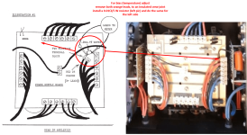 pic3 - SA-4e PS board.png486.2 KB · Views: 67
 -
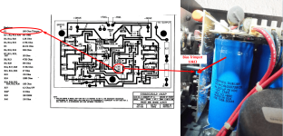 pic4 - SA-4e FE board.png487.4 KB · Views: 91
 -
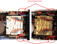 pic5 - SA-4e number of transistors.png395.5 KB · Views: 67
 -
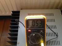 pic6 - thermo measurement.jpg81.9 KB · Views: 62
 -
Threshold-Standard-Bias-Procedure.pdf253.4 KB · Views: 53
Your emitter resistors must be hidden behind the aluminium heat spreader in your pic 2 , hence the measurement for bias with the method shown in pic 3 reading mVDC across the 0.01 ohm resistor . You might need to pull the sides of so you can get to the front end board and perhaps change the bias pot to one that has the adjust screw on the side so it points to the top of the amp for easier screw driver adjustment. The schematics I have seen for your amp show 24 transistors per channel.
The temp measurement shown in pic 6 is fine - near the centre / top of the heatsink is ideal.
The biasing document is correct, important points are the final bias level, with regards to heatsink temp after 2 hours or more with the lid on.
The temp measurement shown in pic 6 is fine - near the centre / top of the heatsink is ideal.
The biasing document is correct, important points are the final bias level, with regards to heatsink temp after 2 hours or more with the lid on.
- Home
- Amplifiers
- Pass Labs
- Threshold S/550e to SA/4e conversion?