Hi All… UK expat based here in Singapore.
This is actually my first post on diyAudio… so please forgive me if this is in the wrong section or if the attached pictures are too big... or even if this post is a little lengthy.
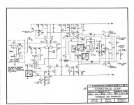
OK, I’ve been reading and gathering as much information as I’ve been able to first, prior to posting. This is having come across a Threshold S/350e power amp locally, for sale.
Due to the age of these amps, I know it’s de rigueur to replace the power filter caps, change the tantalum to an electrolytic cap on the FEB, check (de-solder) and/or replace any output transistors that may have failed and replace the carbon composite resistors due to drifting for something more appropriate… amongst others !
However, before I effectively go ahead and purchase this superb amp and “go to town” on it, I’m by no means an electronics “guru”, but I know enough to refresh these amps and perform upgrades etc. So, would appreciate as much feedback or suggestions as possible from others members on here… and perhaps, if the man himself, Mr. Pass, would be kind enough to provide some additional enlightenment.
The following is what I plan to do, so far…
Perhaps an additional thought to allow closer location of each amp to each speaker without having to cross any of the cables etc., a more intriguing or adventurous idea would be to create a pair of S/350e “hybrid power” amps, using the existing double bridge rectifiers in each amp.
Looking at the schematic, mount a second transformer in each amp with a centre tap (how would this work with both 31v & 50v taps ?) two split the power filter capacitors using a custom sourced pcb then reconfigure and bias one side to run in Class A/AB @ 150w for the LO’s and the other side to run in Class A @ 60w for the MID’s and HI’s… would anyone like to enlighten if this is doable somehow ?
Other suggestions or input is welcome and greatly appreciated.
TIA… Phil.
This is actually my first post on diyAudio… so please forgive me if this is in the wrong section or if the attached pictures are too big... or even if this post is a little lengthy.
OK, I’ve been reading and gathering as much information as I’ve been able to first, prior to posting. This is having come across a Threshold S/350e power amp locally, for sale.
Due to the age of these amps, I know it’s de rigueur to replace the power filter caps, change the tantalum to an electrolytic cap on the FEB, check (de-solder) and/or replace any output transistors that may have failed and replace the carbon composite resistors due to drifting for something more appropriate… amongst others !
However, before I effectively go ahead and purchase this superb amp and “go to town” on it, I’m by no means an electronics “guru”, but I know enough to refresh these amps and perform upgrades etc. So, would appreciate as much feedback or suggestions as possible from others members on here… and perhaps, if the man himself, Mr. Pass, would be kind enough to provide some additional enlightenment.
The following is what I plan to do, so far…
- Replace power filter caps; any recommended value… or is it just a case of the largest value, lowest ESR and highest ripple relative to correct voltage and physical size that will fit ?
- Replace base emitter resistors with Dale NS Series (non-inductive) 1% 2.5w wire wound; any alternative type recommended ?
- Replace (C7) 4.7uf tantalum with electrolytic; low ESR recommended or alternative type for stable and long life ?
- Replace (C4) 220uf electrolytic; low ESR recommended or alternative type for stable and long life ?
- Replace (R37) 6.2Ω 1w carbon composite; any alternative type recommended ?
- Replace (T1) trim pot with multi-turn type for easier adjustment from top of amp; any thoughts on this ?
- Replace (C7,C8,C9,C10) power supply pcb (small) electrolytics with low ESR types; any thoughts on this ?
- Add bypass caps to power filter caps; any recommended value and type ?
- Fit a soft start circuit; any recommended brand ?
- I’ve read somewhere on the internet but it wasn’t explained how, the balanced input impedance can be raised from 600Ω to approximately 50kΩ; any thoughts on this ?
- Replace (Q5) 2N5566 with IFN2N5566 I’ve read it is/can be beneficial to replace this JFET; any thoughts on this ?
- I understand a matched pair of IFN2N5566’s is required for the above point; any thoughts on this ?
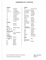
- I’ve read about one member; kevd having significant trouble some time ago trying to bias his amp which eventually turned out to be an incorrect CNY17-4Z optocoupler instead of a CNY17-3. I understand the FEB on these amps have (U1,U3,U5) three (3) CNY17-4Z optocouplers; do all three (3) need to be replaced as per component list, or just U3 adjacent to the trim pot ?
- I’ve seen pictures of the (C12) 0.15uf/400v replaced with a WIMA polypropylene; any thoughts on this ?
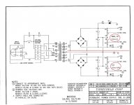
- Considering the idea of replacing the rectifiers with pcb modules utilising SiC Schottky diodes mounted on heatsinks; any thoughts on this ?Based on experience working with PA systems, I know all too well in general it takes more “energy” or power to drive the LO end, compared to the MID’s and HI’s. So this is what I have in mind at the time of refreshing this amp; my plan is to keep this amp as standard and run it Class A/AB @ 150w per side for the moment. Then, if I purchase a second amp, reconfigure it to an SA/3.9e and run it Class A @ 60w per side for driving the MID’s and HI’s, while using the first amp and run it Class A/AB @ 150w per side for driving the LO’s… this is to allow for “headroom”.
Perhaps an additional thought to allow closer location of each amp to each speaker without having to cross any of the cables etc., a more intriguing or adventurous idea would be to create a pair of S/350e “hybrid power” amps, using the existing double bridge rectifiers in each amp.
Looking at the schematic, mount a second transformer in each amp with a centre tap (how would this work with both 31v & 50v taps ?) two split the power filter capacitors using a custom sourced pcb then reconfigure and bias one side to run in Class A/AB @ 150w for the LO’s and the other side to run in Class A @ 60w for the MID’s and HI’s… would anyone like to enlighten if this is doable somehow ?
Other suggestions or input is welcome and greatly appreciated.
TIA… Phil.
Attachments
- Replace power filter caps; any recommended value… or is it just a case of the largest value, lowest ESR and highest ripple relative to correct voltage and physical size that will fit ?
- Replace base emitter resistors with Dale NS Series (non-inductive) 1% 2.5w wire wound; any alternative type recommended ?
- Replace (C7) 4.7uf tantalum with electrolytic; low ESR recommended or alternative type for stable and long life ?
- Replace (C4) 220uf electrolytic; low ESR recommended or alternative type for stable and long life ?
- Replace (R37) 6.2Ω 1w carbon composite; any alternative type recommended ?
- Replace (T1) trim pot with multi-turn type for easier adjustment from top of amp; any thoughts on this ?
- Replace (C7,C8,C9,C10) power supply pcb (small) electrolytics with low ESR types; any thoughts on this ?
- Add bypass caps to power filter caps; any recommended value and type ?
- Fit a soft start circuit; any recommended brand ?
- ...just a case...
- Metal Oxide 3W 5%
- just proper brand/name type elko, or small red Wima block, if space permits
- just proper brand/name type elko
- 1 or 2W Metal Film
- if you're Chicken as ZM, multiturn is a must
- just proper brand/name type elko
- anything bellow 4u7 is just for looks; here also just proper brand/name type solid cap
- NTC 10R, proper physical size meaning proper current; CL60 tried and proven
- I’ve read somewhere on the internet but it wasn’t explained how, the balanced input impedance can be raised from 600Ω to approximately 50kΩ; any thoughts on this ?
- Replace (Q5) 2N5566 with IFN2N5566 I’ve read it is/can be beneficial to replace this JFET; any thoughts on this ?
- I understand a matched pair of IFN2N5566’s is required for the above point; any thoughts on this ?
- I’ve read about one member; kevd having significant trouble some time ago trying to bias his amp which eventually turned out to be an incorrect CNY17-4Z optocoupler instead of a CNY17-3. I understand the FEB on these amps have (U1,U3,U5) three (3) CNY17-4Z optocouplers; do all three (3) need to be replaced as per component list, or just U3 adjacent to the trim pot ?
- I’ve seen pictures of the (C12) 0.15uf/400v replaced with a WIMA polypropylene; any thoughts on this ?
- Considering the idea of replacing the rectifiers with pcb modules utilising SiC Schottky diodes mounted on heatsinks; any thoughts on this ?Based on experience working with PA systems, I know all too well in general it takes more “energy” or power to drive the LO end, compared to the MID’s and HI’s. So this is what I have in mind at the time of refreshing this amp; my plan is to keep this amp as standard and run it Class A/AB @ 150w per side for the moment. Then, if I purchase a second amp, reconfigure it to an SA/3.9e and run it Class A @ 60w per side for driving the MID’s and HI’s, while using the first amp and run it Class A/AB @ 150w per side for driving the LO’s… this is to allow for “headroom”.
- that tonight, will have more time
- if amp works and DC Offset is OK, do not touch them
- if changing, and you're using single JFets, you must use matchd pair for LTP
- if amp works, do not change optos
- read comments above for (all) caps
- if that rattles you cage in appropriate manner, replace them
Oops… sorry folks, looks like some of my editing went astray on the last bullet point… too late to edit !
Thanks for your suggestions Zen Mod. Just a few additional points;
Thanks for your suggestions Zen Mod. Just a few additional points;
- What’s your rational of metal oxide’s over wire wound’s on the emitters ?
- Small red WIMA block cap… polypropylene, polyester or polyethylene… any preference ?
- 4.7uf bypass caps would be minimum… correct ?
- Acceptable DC offset for these particular amps ?
- even if some hear difference, some don't - MOX is simply better resistor than WW
- don't care; any is better than elko
- yes
- any amp, +/-100mV; less, the better
simply, everything is up to you

The Emitter resistors are 1 ohm right?
Add a snubber circuit for the transformer to the list. Quasimodo, cheapomodo are two terms to look up regarding that. Regarding the discrete diodes, you could probably mount all of the rectifiers to a piece of 3/8" aluminum bar or something and just mount the bar to the bottom plate with two holes, one on each end of the aluminum.Considering the idea of replacing the rectifiers with pcb modules utilising SiC Schottky diodes mounted on heatsinks; any thoughts on this ?Based on experience working with PA systems, I know all too well in general it takes more “energy” or power to drive the LO end, compared to the MID’s and HI’s. So this is what I have in mind at the time of refreshing this amp; my plan is to keep this amp as standard and run it Class A/AB @ 150w per side for the moment. Then, if I purchase a second amp, reconfigure it to an SA/3.9e and run it Class A @ 60w per side for driving the MID’s and HI’s, while using the first amp and run it Class A/AB @ 150w per side for driving the LO’s… this is to allow for “headroom”.
Attachments
Check with Zen Mod since these aren't metal oxide but rather metal film but I think these will work:
https://www.digikey.com/en/products/detail/panasonic-electronic-components/ERX-3SJR68/36509
https://www.digikey.com/en/products/detail/panasonic-electronic-components/ERX-3SJR68/36509
I don't see a problem with the Panasonics since Papa used them in the Pass Labs products. 🙂
Have fun with your refresh/restoration.
Have fun with your refresh/restoration.
Metal Oxide or Metal Film, whatever
through hole, 3W, 5%
value of interest, and you're good
I don't even care who made them, as long I got them from reputable source
through hole, 3W, 5%
value of interest, and you're good
I don't even care who made them, as long I got them from reputable source
I grab the Panasonics whenever I make an order from Digikey because when I grow up, I want to be like Mr Pass.
He's very slippery Fish ...... so task being daunting one

I think that it's time to re-cap my original SA 3.9e. Does anyone know of a power supply cap in 2023 that will match the physical dimensions of the original Mepco 27,000uf/ 85v caps?
VintageAmp may have some insight. The big thing is the diameter as you would want to fit into the original cap bands. I believe there are three holes drilled into the bottom plate of the chassis to accommodate the cap band.
Get the height close so long as it doesn't touch the lid and the wiring will reach the terminals. I suspect you will end up with something with higher capacitance.
Epcos are good. Kemet ALS or similar caps are also nice.
Get the height close so long as it doesn't touch the lid and the wiring will reach the terminals. I suspect you will end up with something with higher capacitance.
Epcos are good. Kemet ALS or similar caps are also nice.
Thanks so much, Mike! I just took a look at both Mouser and DigiKey and it appears that the form factor of those computer-grade capacitors is becoming very rare.
I've got some Kemets on the way! Check out the life spec!
KEMET Series ALS30
Capacitance 33000 µF
Voltage - Rated 63 V
ESR (Equivalent Series Resistance) 10mOhm @ 100Hz
Lifetime @ Temp. 18000 Hrs @ 85°C
Ripple Current @ Low Frequency 17.4 A @ 100 Hz
Ripple Current @ High Frequency 18 A @ 10 kHz
Impedance 9 mOhms!!
Lead Spacing
0.874" (22.20mm)
Size / Dimension
2.008" Dia (51.00mm)
Height - Seated (Max)
4.213" (107.00mm)
Oh yes those kemets Will outlast both of us probably.
I have some in my favorite amplifier. They are great. Amplifier is dead quiet
I have some in my favorite amplifier. They are great. Amplifier is dead quiet
I recently outfitted the power supply of my Threshold CAS-2 with Kemet ALS30 15,000 uF, 63V caps. The improvement was measurable and very noticeable while listening.
- Home
- Amplifiers
- Pass Labs
- Threshold S/350e Refresh