Today I purchased a beautiful Threshold setup locally, including an S/300 Series II amp and a FET One Series II. Both units have a sticker that indicates they've been factory updated to the e/series STASIS topology. I bought them from a local audio dealer who bought them from the original owner.
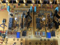
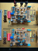
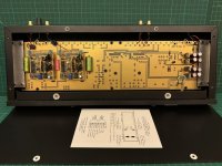
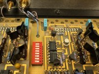
The preamp has jacks for the MC inputs, but the MM input is blocked off. Inside the preamp, the circuit board looks very different from other photos of FET Ones I've seen. Mine is more similar to a FET Nine I've seen a photo of, with little daughterboards attached to the main board, which presumably host the preamp circuits. The phono preamp boards have a DIP switch nestled between them, which, if it's similar to the FET Nine, allows different impedance and capacitance settings to be selected. But I haven't managed to find a manual for this particular mod of this preamp. Do any Threshold experts here have any insight to the switch positions for the FET One Series II with e/series mod?
I've attached a couple of photos of my unit. Thanks for any help!
Attachments
you can easily make your own table, if you put ohmmeter in input RCA (red to mid , black to sleeve), then fiddle with multiswitch
if reworked to Fet 9, things are more complicated
anyhow, you have both OM and SM on HiFi Engine
too big to post them here
though, 3 of 4 things you can download from here (just checked) https://www.zenmod.in.rs/treshold-treasure-while-papa-was-there-fet-9/
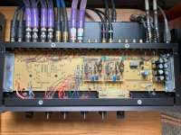
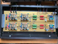
I'm not a Threshold expert, I am an owner, my FET10-HL has the same factory Stasis modification, here are pics:
The Stasis gain stage should look familiar to you, the other addition was a pair of XLR outputs.
The Stasis gain stage should look familiar to you, the other addition was a pair of XLR outputs.
Attachments
I also have the Threshold FET10Pe phono stage, here are pics:
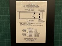
The DIP switches and gain stages should also look familiar, I included the page from the owners manual which describes the Dip switch positions.
Hope this helps.
The DIP switches and gain stages should also look familiar, I included the page from the owners manual which describes the Dip switch positions.
Hope this helps.
Attachments
Thanks all for the excellent input!
I took some measurements of the effects of the 8-pin DIP switch on the phono channel inputs. My meter (Fluke 115) has a capacitance setting but it always reads OL. It probably can't go down to the picofarad range.
all switches off
R Impedance = 44.4 kohm
L Impedance = 47.5 kohms
I'm surprised that the right channel is so off from the 47k I was expecting from the other preamps.
Switches:
1 unknown capacitance value?
2 unknown capacitance value?
3 R Impedance = 100.8 ohms
4 R Impedance = 48.3 ohms
3 + 4 R Impedance = 33.1 ohms
5 L Impedance = 48.2 ohms
6 L Impedance = 100.3
5 + 6 L Impedance = 32.9 ohms
7 unknown capacitance value?
8 unknown capacitance value?
So it's actually configured differently than all of the other preamps you sent and I took a look at.
With my MC cartridge I've started with the 100 ohm setting and will listen to see if I can hear differences with the presumed capacitance settings. One thing I did notice is that without the two jumper pins jumped, I get very low gain out of the phono input. So that's similar to the FET Ten PC, although that has a 3 position jumper and this preamp has a 3 position jumper with one of the pins trimmed. So I guess for this preamp, jumpers disconnected = MM, jumpers connected = MC.
As I'm looking at this, I'm super curious to know if the e/series mods are actually an improvement over the original FET One design. Of course I don't have any way to compare but it has me wondering...

I dug a bit further into this today. I removed the phono boards and looked at the circuitry underneath. The full switch functionality is:
Right Channel Settings:
1 R Capacitance = 47 pF
2 R Capacitance = 15 pF
1 + 2 R Capacitance = 62 pF
3 R Impedance = 100.8 ohms
4 R Impedance = 48.3 ohms
3 + 4 R Impedance = 33.1 ohms
Left Channel Settings:
5 L Impedance = 48.2 ohms
6 L Impedance = 100.3
5 + 6 L Impedance = 32.9 ohms
7 L Capacitance = 15 pF
8 L Capacitance = 47 pF
7 + 8 L Capacitance = 62 pF
I've attached a photo of the switch circuitry in case it's useful to anyone in the future.
Attachments
Update on the above, what I called 15pF caps are actually 150pF caps. So the updated switch functionality is:
1 R Capacitance = 47 pF
2 R Capacitance = 150 pF
1 + 2 R Capacitance = 197 pF
3 R Impedance = 100.8 ohms
4 R Impedance = 48.3 ohms
3 + 4 R Impedance = 33.1 ohms
5 L Impedance = 48.2 ohms
6 L Impedance = 100.3
5 + 6 L Impedance = 32.9 ohms
7 L Capacitance = 150 pF
8 L Capacitance = 47 pF
7 + 8 L Capacitance = 197 pF
My right channel phono board has two blown NPD5566 dual JFETs. I'm going to replace those parts, but I wonder if I do that if I need to recalibrate it. These boards have trimpots, reference designator P1, in series with the LF351N op amp output. Does anyone have any insight in how to adjust this trimpot to factory specs? The FET Nine E service manual I'm referring to seems to have no insight. Screenshot of the phono input board is attached.
Attachments
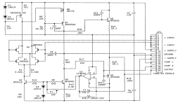
Hi tenelson, The trim pots contol the DC offset servo circuit. The circuit should self correct for DC offset. If not, the small cap next to the trimmer should have 3-5 volts. They do tend to go wild sometimes and then the offset becomes a problem. The DCV sets the feedback to the op amp LF351 that servos the amp output.
VintageAmp, thanks for the clarification. I've noticed that the circuit does tend to go wild, putting either +15v or -15 on the preamp card output. I found that replacing the original single turn trimmers with modern multi turn trimmers made it much easier to dial it into the range where there output voltage was close to zero. Since then, the preamp seems to be stable.
The preamp is still noisy after a full recap and diode replacement in the power supply. I guess I need to look for better power supply upgrades because it all seems to come from the external power supply.
The preamp is still noisy after a full recap and diode replacement in the power supply. I guess I need to look for better power supply upgrades because it all seems to come from the external power supply.

- Home
- Amplifiers
- Pass Labs
- Threshold FET One Series II E/series version