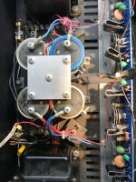
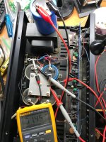
Hi all. I bought this CAS1 recently and after replacing an arching power switch noticed an unequal rail voltage . All rails measure approx 33 volts till you get to that blue cap. 50 volts. I have never run into this before. But, I have never had just 1 cap replaced. Both ac inputs to the bridge react run 76 volts. Meter is rms reading
I probably will replace these caps and the tantalum’s too but thought this wierd.
Thank you, Rick
I probably will replace these caps and the tantalum’s too but thought this wierd.
Thank you, Rick
Attachments
Is it possible that one rail fuse is blown, unloading that capacitor? Is there much less ripple on that capacitor?
Check the output DC offset and bias for that channel.
Check the output DC offset and bias for that channel.
Any test equipment other than a DVM?
Seems that someone else thought the one capacitor was the problem.
Of course, it could not be.
Seems that someone else thought the one capacitor was the problem.
Of course, it could not be.
Thanks for the schematic.
There a few things that baffle me. Sheet 2 of the PDF indicates the supply rails are +/-49V, but you report about 33, 33, 33, 50 VDC. The secondaries don't appear to have a center-tap, if the schematic is to be believed. Not sure what defines the how the peak-to-peak supply rails accommodate the lack of a center-tap. Maybe it doesn't matter... ? What AC voltage do you see across the secondaries? They should help predict expected total DC Pk-Pk rail voltage.
I'm sure your amps have the transformer primaries wired in parallel, but I'm unnerved by series connection of two separate transformers, operated at 240VAC. Consider if one channel is driven heavily, but the other channel is at no signal. First channel PS sees heavy load, the other PS light load. The two transformers will not share 240V equally; the undriven channel will be be over-voltaged. It's akin to wiring a 150W, 120V bulb in series with a 40W, 120V bulb and applying 240V. The 40W bulb won't survive.
Another thought: measure-rail-to rail voltage in each channel.
Last edited:

You may have lost the reference to common. Connect your meter directly across each capacitor.
Yes, measure resistance from that center screw to the chassis. Should be somewhere from 0 to 10 ohms,
depending if there is a ground noise network. Are all 5 screws tight?
How about the ripple voltage on each capacitor?
depending if there is a ground noise network. Are all 5 screws tight?
How about the ripple voltage on each capacitor?
I just wanted to thank Nelson Pass for his support of DIy! Where else can you have the designer of a piece of audio gear made a long time ago, chime in with his help? Impressive
- Home
- Amplifiers
- Solid State
- Threshold CAS1 unequal rail voltage