Has there been a clone DIY PCB designed for a CAS1 clone using modern obtainable transistors?
I am interested in a fully cascoded BJT Nelson Pass design. The CAS1 looks to be the least complex of all of the Threshold schematics that I have looked at. It would seem a good first effort.
I am interested in a fully cascoded BJT Nelson Pass design. The CAS1 looks to be the least complex of all of the Threshold schematics that I have looked at. It would seem a good first effort.
I've looked into it; meaning I've spent 45 minutes fooling around with digikey.com and a calculator. I think I believe it's possible to emulate/duplicate/improve-upon with modern parts. BUT fire up your most potent Google-Fu and look at the Images of the original. It was dual mono with two transformers. That might be the most time-consuming, money-consuming, chassis-volume-consuming part of the whole project.
Hello Mark
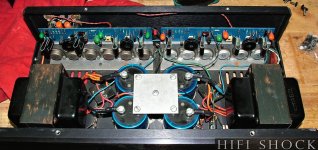
Thank you for the reply. As you recommended, I foo'd a picture and have attached it here for the sake of discussion.
it looks like dual mono power supplies with a common ground between the channels.
The striking thing to me is that it appears that the output transistors are sinked (sunk?) to the bottom of the chassis along with the bridge rectifiers. I see no actual heat sink anywhere. The drivers have clip-on heat sinks. This amp must be super efficient if it can produce 75 watts with virtually no heat sink.
I agree that most of the cost will be chassis/power supply/heat sinks. Same for many power amp DIY endeavors.
For bench development for this project, I have a pair of Kikusui bench supplies that are capable of 35V @ 20A continuous. I will not need to purchase any power supply parts for the initial what-if stage. I also have several sizable heat sinks that I can use.
For the front end and VAS, I have devices that I think will work. My question is what devices will work for the final stage?
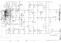
The schematic that I have is attached. I am looking for input as to the correctness of this schematic.
Thank you for the reply. As you recommended, I foo'd a picture and have attached it here for the sake of discussion.
it looks like dual mono power supplies with a common ground between the channels.
The striking thing to me is that it appears that the output transistors are sinked (sunk?) to the bottom of the chassis along with the bridge rectifiers. I see no actual heat sink anywhere. The drivers have clip-on heat sinks. This amp must be super efficient if it can produce 75 watts with virtually no heat sink.
I agree that most of the cost will be chassis/power supply/heat sinks. Same for many power amp DIY endeavors.
For bench development for this project, I have a pair of Kikusui bench supplies that are capable of 35V @ 20A continuous. I will not need to purchase any power supply parts for the initial what-if stage. I also have several sizable heat sinks that I can use.
For the front end and VAS, I have devices that I think will work. My question is what devices will work for the final stage?
The schematic that I have is attached. I am looking for input as to the correctness of this schematic.
Attachments
Thanks. I just printed it out to have a look.
Do you know if this has ever been entered into LT Spice and/or Eagle CAD?
Do you know equivalent part modern numbers for the output N and P transistors?
Do you know if this has ever been entered into LT Spice and/or Eagle CAD?
Do you know equivalent part modern numbers for the output N and P transistors?
No and no; sorry.
Perhaps it might be possible to abandon the quest for "equivalent" components, and instead begin a search for "best possible choice among today's available" components. In other words, think of yourself as a designer and not as a purchasing agent.
Perhaps it might be possible to abandon the quest for "equivalent" components, and instead begin a search for "best possible choice among today's available" components. In other words, think of yourself as a designer and not as a purchasing agent.
Homework. It was time for some homework.
Attached is a picture that I found. The output transistors are NEC 2SD287C and 2SB539A.
The NEC datasheet is attached.
I will start looking for TO3 plastic equivalent parts. If anyone wants to chime in with suggestions, that will be welcome.
Attached is a picture that I found. The output transistors are NEC 2SD287C and 2SB539A.
The NEC datasheet is attached.
I will start looking for TO3 plastic equivalent parts. If anyone wants to chime in with suggestions, that will be welcome.
Attachments
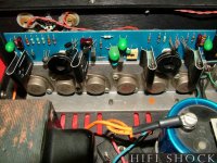
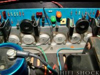
That's the left half of the photo attached to post #3. The right half of the same photo shows six TO-3 transistors, all with the "Bat Wing" Motorola logo. Which suggests that the amplifier may have been repaired and the output devices for one channel were replaced. But which is the original and which is the replacement?
Here is a reply from NP in a 2004 thread.
"Those were Motorola 2N5878 and 76, 80 volt, 4 MHz devices.
You can replace them with most ordinary TO-3's with a 4 MHz
bandwidth (Ft)"
"Those were Motorola 2N5878 and 76, 80 volt, 4 MHz devices.
You can replace them with most ordinary TO-3's with a 4 MHz
bandwidth (Ft)"
careful with that axe, Eugene
I mean - Ft

Always looking for a good CB radio amplifier.
Fortunately I have access to a modern scope with 2 GHz bandwidth. If there is a problem, I will be able to see it.
then you're good
handful of tiny caps , and all is well
though , best to use them just as lucky charm , without soldering them in circ
🙂
handful of tiny caps , and all is well
though , best to use them just as lucky charm , without soldering them in circ
🙂
Here is a possibility for a modern output complementary pair. Ft looks better and gain looks better and Vceo looks better compared to the original parts.
Those look terrific. If you want to use 4 MHz fT devices (which I don't think is a great idea), MJL21195 / MJL21196 seem like a close match: .pdf datasheet
_
The MJL21195 costs more. I will order a few of each of the N and P parts that I posted and perform some curve tracing to see how they measure.
The gain vs collector current curve will be interesting compared to the data sheet curve.
The gain vs collector current curve will be interesting compared to the data sheet curve.
See how you like the MPSA18 which is in stock at Mouser. You might also consider the 2N5089, which too is in stock at Mouser.
Thank you for those. Interesting that On Semi discontinued these and Central Semi picked them up. Also interesting that there are no curves in the datasheet.
It will also be interesting to see how many matches occur. I will order 25 pcs with hopes of at least a couple of matched pairs.
- Status
- Not open for further replies.
- Home
- Amplifiers
- Pass Labs
- Threshold CAS1 clone?