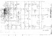
See the attached schematics
I want to replace the tantalums as the Mr. Pass has suggested in some other topics discussing Threshold products.
In particular this amplifier has 2x 47uf/20v tantalum caps at the power stage, 1x 47uf/20v tantalum coupling cap at the line stage and not-sure-what-that-part-does stage 220uf/10v.
My plan is to use some well known caps such as elna silmic 2 but I am wondering if I can swap the input coupling cap for a better one - polypropylene film cap. 47uf film caps are really expensive, I wonder if I can replace it with lower nominal caps... For instance it does not have to be rated for such high voltage - 20v. If I am going to solder in a bipolar cap. I could do with 5v max - as far as I know the amp input sensitivity is bellow 2 volts.
What about its capacitance? My almost-non-existant electronics knowledge tells me that a cap and the input impedance form a high pass filter. I am not entirely sure what's the input impedance, but on some booklet I've seen it stating 75k. Hell, I believe we can agree that 10k would be the absolute minimum. With a 10k input impedance and 10 times lower capacitance 4.7uf cap I will have an f3 of ~4hz. And in case the impedance is actually 75k, f3 is even lower.
I am wondering if all this my rambling make any sense about swapping the input capacitor for a lower value polypropylene capacitor instead of maintaining the same nominal 47uf electrolytic.
Do you think it is safe to conduct this experiment in practice?
Thanks!
Attachments
Last edited:
Is there some general rule of thumb for picking the bypass cap value?use elco bypassed with 1uF solid
Wasn't aware of this bypassing practice. It seems that it does make sense - elcos impedance relates to the frequencies and bypass film cap partially address this - they are faster, tend have lower impedance at higher freq.
Now I must bypass every capacitor I will find in my life 😀.