Hey all,
So, a few weeks ago, I was biasing my 400A. As luck would have it, the alligator clip fell off my multimeter and shorted one of the .68 ohm emitter resistors (PNP, right channel) to the iron core of the transformer (ground). Yikes! Output fuse blew right away, and after that, the right channel wouldn't heat up, or amplify anything (understandably).
I have since replaced ALL 16 output transistors with ON Semi MJ15003G/4G, the two driver transistors (marked FT317/417) with MJE15030G/31G, and the three electrolytic caps (470uF, and 2x 47uF) of the same value, the 470uF with a higher voltage cap, which is fine. The original caps tested fine, but probably needed to be replaced anyways, since this is a ~30 year old amplifier. The silvered mica caps all tested fine. All the diodes and resistors test good, including the TO-3 VARO dual-series diode on the heatsink.
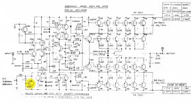
I've attached the schematic which almost exactly matches the layout of my 400A (my serial number is A80011880, 1980! Probably one of the last off the line!). The Previous owner said he had it sent in to Threshold in the mid-90s for repairs, and can't remember if he had an upgrade done or not.
Currently, I'm measuring -57V DC across the output terminals, which tells me that the PNP side of the circuit is completely floored/ON. The next thing to check could be the A92s in the bias network, or the A42s in the input stage.
So, any ideas? Did I substitute the wrong parts anywhere?
Perhaps I'll get lucky enough to have the One and Only Nelson Pass help me out on this one 🙂
Thanks for the help!
So, a few weeks ago, I was biasing my 400A. As luck would have it, the alligator clip fell off my multimeter and shorted one of the .68 ohm emitter resistors (PNP, right channel) to the iron core of the transformer (ground). Yikes! Output fuse blew right away, and after that, the right channel wouldn't heat up, or amplify anything (understandably).
I have since replaced ALL 16 output transistors with ON Semi MJ15003G/4G, the two driver transistors (marked FT317/417) with MJE15030G/31G, and the three electrolytic caps (470uF, and 2x 47uF) of the same value, the 470uF with a higher voltage cap, which is fine. The original caps tested fine, but probably needed to be replaced anyways, since this is a ~30 year old amplifier. The silvered mica caps all tested fine. All the diodes and resistors test good, including the TO-3 VARO dual-series diode on the heatsink.
I've attached the schematic which almost exactly matches the layout of my 400A (my serial number is A80011880, 1980! Probably one of the last off the line!). The Previous owner said he had it sent in to Threshold in the mid-90s for repairs, and can't remember if he had an upgrade done or not.
Currently, I'm measuring -57V DC across the output terminals, which tells me that the PNP side of the circuit is completely floored/ON. The next thing to check could be the A92s in the bias network, or the A42s in the input stage.
So, any ideas? Did I substitute the wrong parts anywhere?
Perhaps I'll get lucky enough to have the One and Only Nelson Pass help me out on this one 🙂
Thanks for the help!
Attachments

pick out - one by one ! - small transistors from pcb and check it with diode test on your DMM
check - if good - solder it back , then to next one
if bad - replace , then to next one
it seems slowest , but it is most secure way , at least for someone without 10.000 miles in repair biz
be sure to use ( in case of need to replace ) matched ones in input LTP (6571)
all others aren't critical , regarding matching
😉 each time , looking at those old circs , I'm amused how cunning chap was that Treshold guy
pick out - one by one ! - small transistors from pcb and check it with diode test on your DMM
check - if good - solder it back , then to next one
if bad - replace , then to next one
it seems slowest , but it is most secure way , at least for someone without 10.000 miles in repair biz
be sure to use ( in case of need to replace ) matched ones in input LTP (6571)
all others aren't critical , regarding matching
😉 each time , looking at those old circs , I'm amused how cunning chap was that Treshold guy
I'm going to look at each transistor one by one. I'm wondering if anyone has any other ideas though, or if anyone has had a similar problem.
Also, when I first opened up the amp, I noticed that the big 470uF cap was installed backwards! I confirmed by tracing the "+" mark on the PCB to the 390 ohm resistor and 300pF mica cap. This was on both channels, I replaced the caps on the other (working) channel as well.
I can fix an amp locating one bad transistor
but I don't like them soon on the bench again 😉
so , at least speaking of big honkin' ones , having some sort of fireworks prior to being on bench ( and your Treshold certainly is one of them ) I like to check each semi
but I don't like them soon on the bench again 😉
so , at least speaking of big honkin' ones , having some sort of fireworks prior to being on bench ( and your Treshold certainly is one of them ) I like to check each semi
I can fix an amp locating one bad transistor
but I don't like them soon on the bench again 😉
so , at least speaking of big honkin' ones , having some sort of fireworks prior to being on bench ( and your Treshold certainly is one of them ) I like to check each semi
I know what you mean! That's why I replaced all the output transistors, even though half of them tested good.
I'll check each one when i get a chance.
Thanks.
Okay, I found one bad transistor so far. The A42 on the very bottom-left of the schematic. I've attached the schematic with the part highlighted.
I also noticed that my board does not have ANY thermistors for bias compensation, only a thermal breaker. Every schematic I have of the 400A shows two thermistors per channel. Should I add these to the circuit?
I also noticed that my board does not have ANY thermistors for bias compensation, only a thermal breaker. Every schematic I have of the 400A shows two thermistors per channel. Should I add these to the circuit?
Attachments
I dont really know because I have never looked inside one but usually the thermal compensation is mounted on heat sink or directly on an o/p transistor.. that being said look around ....
Mr Rollins had several of those beast years ago...weighed a ton each.
Have fun , El
Mr Rollins had several of those beast years ago...weighed a ton each.
Have fun , El
- Status
- Not open for further replies.
- Home
- Amplifiers
- Pass Labs
- Threshold 400A, Need Help!