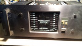
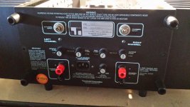
Need some advise. I was given a Threshold 400A Cascode from my buddy, to keep. The problem, it blows the rail fuses as soon as you turn it on. I popped the top off and just visually looked around. Looked very clean, no sign of any blown or distressed parts. I've built a few solid state and tube power amps, power supply's and such, pretty basic stuff, but am not a savvy bench tech. I own a variac, dim bulb tester and a scope, (with limited knowledge on it). I assume there's no "do this and there's your problem" answer but I hate to just let it sit there. I want to use it! What do you think?
Attachments


- how to repair an amp ?
- simple , take it and repair it .......
-best way to catch a wabbit ?
-simple , put some salt on his tail .........

I'm always going with PSU check first (shorties , blown diodes,shorted caps) , then output side (one channel , then other) - checking outputs for shorts then conduction (diode test)
that would need dismantling either emiter/base resistors or transistors itself from circuit
then front end - first for shorties then , if needed , dismantling each semiconductor from pcb and checking it with diode/megaohm test and functionality test (if needed)
so , see things are simple ....... even if I didn't mention setting/testing procedure afterwards

- simple , take it and repair it .......
-best way to catch a wabbit ?
-simple , put some salt on his tail .........
I'm always going with PSU check first (shorties , blown diodes,shorted caps) , then output side (one channel , then other) - checking outputs for shorts then conduction (diode test)
that would need dismantling either emiter/base resistors or transistors itself from circuit
then front end - first for shorties then , if needed , dismantling each semiconductor from pcb and checking it with diode/megaohm test and functionality test (if needed)
so , see things are simple ....... even if I didn't mention setting/testing procedure afterwards
With rail fuses removed, check power supply output positive and negative voltages.
With no power, check if any short at the + and - rails of circuitry to the ground.
This thread may be useful :
http://www.diyaudio.com/forums/pass-labs/271817-threshold-4000-repair-need-some-help.html
With no power, check if any short at the + and - rails of circuitry to the ground.
This thread may be useful :
http://www.diyaudio.com/forums/pass-labs/271817-threshold-4000-repair-need-some-help.html
Ok ZM, I took your advise. Got some salt, went outside...... probably easier to work on the amp instead I'll start with the PSU. And nec3, thanks for the tips. Question, would it be ok to desolder the four wires for the VU meters so I could take the front off for easier access?
I'll start with the PSU. And nec3, thanks for the tips. Question, would it be ok to desolder the four wires for the VU meters so I could take the front off for easier access?Take pictures, many pictures before desoldering and dismantling. This is a very useful tips - trust me! ;-)
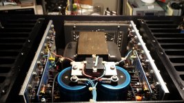
Ok, so I decided to start taking it apart and yes, I have taken a ton of pictures so far. Anyway, here is what I have found so far.
1. One of the output transistors has been replaced so it has been worked on before. ( I circled a second one on the right because I'm not sure if it's original or not.)
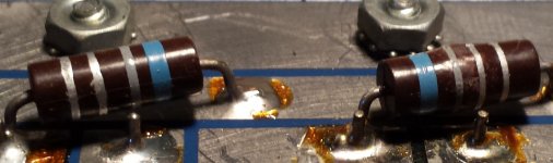
2. One of the 0R68 emitter resistors looks puffy
Posting pictures so you can have a look.
1. One of the output transistors has been replaced so it has been worked on before. ( I circled a second one on the right because I'm not sure if it's original or not.)
2. One of the 0R68 emitter resistors looks puffy
Posting pictures so you can have a look.
Attachments
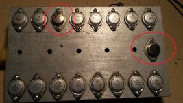

just those with CLASSAsomething are looking as genuine (as from factory) outputs
resistor - it certainly looks poofed
resistor - it certainly looks poofed
I would hav changed all output-transistors (eqvivalent is recomanded in another thread). Change resistors too!
And all electrolytic caps.
Careflly check all solderings, meashure for unwanted shorts and use variac to start amp 🙂
And all electrolytic caps.
Careflly check all solderings, meashure for unwanted shorts and use variac to start amp 🙂
unfortunately , yes
those transistors need to be matched per channel
N one matched group
P one matched group
it would be too ambitious to try matching so many of them N to P
those transistors need to be matched per channel
N one matched group
P one matched group
it would be too ambitious to try matching so many of them N to P
To recap, I need to replace all output transistors with matched N's and matched P's, replace all electrolytics and 0R68 resistors and reflow all solder joints. Yikes. Ok, not saying I can't do that but will have to think on it for a bit. Thanks you guys for all the advice.
The single one inn the middle with the V is a diode. They never break.
No, you probably don't have to replace them all, and they don't have to
be matched. At the factory, we tested them to ensure that they all had
decent current gain (back then, the populations from Motorola had a
good percentage of very low gain devices).
Even the poor current gain transistors worked, we just got a more consistent
product with selecting.
The original parts were house marked 2N5878 and 2N5876, which were
4 Mhz Ft.
😎
I'll look on Digikey and see what there is to replace them.
On-Semi makes them, Digikey has them in stock, about $5 each
MJ15022
MJ15023
MJ15024
MJ15025
They should drop right in, and are more rugged than the originals - actually
years later Threshold switched over to them.
😎
MJ15022
MJ15023
MJ15024
MJ15025
They should drop right in, and are more rugged than the originals - actually
years later Threshold switched over to them.
😎
exactly
don't hurry - let it sit and enjoy in thinking and planning
best way to learn thing or two
don't hurry - let it sit and enjoy in thinking and planning
best way to learn thing or two
Nelson and Zen Mod, thanks for stepping in. I was actually moving in the direction of putting it up on the shelf for now, but I really want to hear it sooooo, back on the bench. I'll keep you updated.
Ok, this thread was started over two years ago. I've made zero progress on this amp. Just been sitting there. I feel like there's someone out there that would fix it and love it. I love it too but apparently not enough to fix it!( read procrastinator). With that in mind, it's for sale, or trade. I didn't post it in the swap meet because anybody interested can catch up on the history from this thread.
If it's a trade, here's stuff I'm looking for:
1. 6C33C tubes
2. Single ended output transformers
3. PP output transformers for EL34's
4. Tube amp stuff
If it's a sale, make an offer.
Please make all offers, sale or trade, through PM. To the moderators, feel free to move this to the swap meet if it should be there instead.
Attachments


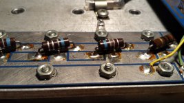

Just as an aside, the emitter resistors used look like the old TRW/IRC BWH series, which uses a fiberglass core resistive element like the "cement box" power resistors, but with a molded phenolic surround rather than a ceramic tub filled with cement. When they are overstressed, the phenolic wrap on the BWH resistors tends to puff up like shown in the photo. This likely indicates the output device(s) that bought the farm. I'd be tempted by this amp, but I already have enough wounded amps in need of repair (I spend most of my time on new designs).
Last edited:
I'd love to give it a try to ressurect it, and it's propably the only way to get my hands on some real Papa-amp as well...
When they are overstressed, the phenolic wrap on the BWH resistors tends to puff up like shown in the photo. This likely indicates the output device(s) that bought the farm.
Maybe not. I have seen cases where the resistor puffed but the transistor
was OK, having survived an over-current.
Would you use same kind of resistors today or replace them with the type used in ACA and other FirstWatt amps? …..I think they are metal film power resistors (not wire wound).
Was that an amp that was at the price level about 6000 USD or so......at the time they were sold?
Was that an amp that was at the price level about 6000 USD or so......at the time they were sold?
- Home
- Amplifiers
- Pass Labs
- Threshold 400A Cascode