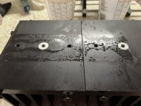
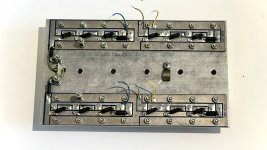
The transformer was tilted beyond what I could tolerate and as you can see, the chassis was grimy. It would be odd to me to do all the work on the boards and then put all of it back in a dirty chassis. Also can redo the wiring a bit.I like it, strip it and start over. I do the same with SAE, GAS, and SUMO using currently available parts.
While I wait for parts for the driver boards, I got into the left channel. Once again, all original. No visible damage to any of the emitter resistors as there was with the right channel.
Here are the testing results from that side:
The filter capacitors show a low ESR value. The thermal paste coverage on this side was far less/non-existent which explains the emitter resistors still looking good. The transistors likely blew more quickly since there was no bond between the heat sinks and the mica. It's obvious to me that two different people worked on the left and right boards as well as output boards when they were made for this amp. The way the emitter resistors were placed was different and in addition, one side has a 2.2k wirewound, the other side has a 2.2k carbon comp. Both original. One side had plenty of thermal paste and tightly torqued bolts (right side), this side had three torqued bolts and two that I unscrewed with my fingers.

Obviously, these transistors all have to go. It isn't a matter of "preference" given the beta values clearly show these are damaged by the same source that shorted four of them.
Does anyone know what/if anything Soderberg is installing for a soft start/inrush current limiter on these amps?
Where are the "if it ain't broke" people from the SA-1 thread?
Here are the testing results from that side:
| Beta values for CLASSA8 & CLASSA6 | |
|---|---|
| NPN | PNP |
| 1) 16 | 1) 114 |
| 2) 50 | 2) Shorted |
| 3) 20 | 3) 172 |
| 4) Shorted | 4) 23 |
| 5) 80 | 5) 202 |
| 6) 25 | 6) Shorted |
| 7) 12 | 7) 258 |
| 8) Shorted | 8) 7 |
The filter capacitors show a low ESR value. The thermal paste coverage on this side was far less/non-existent which explains the emitter resistors still looking good. The transistors likely blew more quickly since there was no bond between the heat sinks and the mica. It's obvious to me that two different people worked on the left and right boards as well as output boards when they were made for this amp. The way the emitter resistors were placed was different and in addition, one side has a 2.2k wirewound, the other side has a 2.2k carbon comp. Both original. One side had plenty of thermal paste and tightly torqued bolts (right side), this side had three torqued bolts and two that I unscrewed with my fingers.

Obviously, these transistors all have to go. It isn't a matter of "preference" given the beta values clearly show these are damaged by the same source that shorted four of them.
Does anyone know what/if anything Soderberg is installing for a soft start/inrush current limiter on these amps?
Where are the "if it ain't broke" people from the SA-1 thread?
Hadley,
I am experiencing exactly the same problems with my 400A dated 03 79.
would you accept my unit ti do a complete refurbish.
my unit is absolutely in original & museum condition, but need a complete rev
I am experiencing exactly the same problems with my 400A dated 03 79.
would you accept my unit ti do a complete refurbish.
my unit is absolutely in original & museum condition, but need a complete rev
Hadley,
I am experiencing exactly the same problems with my 400A dated 03 79.
My unit is absolutely in original & museum condition, but need a complete refurbish.
how can i reach you to discuss the possibility to send my unit .
i live in Europe.
cheers,
Clouseau
I am experiencing exactly the same problems with my 400A dated 03 79.
My unit is absolutely in original & museum condition, but need a complete refurbish.
how can i reach you to discuss the possibility to send my unit .
i live in Europe.
cheers,
Clouseau
I finally have this amp back together. Every transistor has been replaced and matched including on the boards and the outputs.
With all of that and a metal foil potentiometer set at 300Ω in place of the original resistor, I brought up the left side of the amp, I had 75mV of offset at the outputs. Several turns later somewhere toward 500Ω, I had 0mV and stable at the outputs.
Found a decent copy of what I think is the schematic relevant to my unit.
View attachment 1084961
I'm getting my parts situation squared away and noticed the 300Ω resistor on the negative rail below the differential pair. According to the simulator, this is a suboptimal choice. There is a collector current imbalance and dc offset at the outputs in the differential pair if the schematic with this value is followed. If all else is equal and only that resistor is changed to 510Ω, the imbalance is almost completely resolved to the point of the dc offset is negligible. So the question is: what am I missing here?
Additionally, was there any reason why the bias pot wasn't placed between resistors? Seems like a prudent choice to limit adjustment.
With all of that and a metal foil potentiometer set at 300Ω in place of the original resistor, I brought up the left side of the amp, I had 75mV of offset at the outputs. Several turns later somewhere toward 500Ω, I had 0mV and stable at the outputs.
Really looking for a part list and schematic. My tech guy has had my Threshold 4000 is sitting on a shelf in parts for almost a year. He's stuck and needs a value list and a schematic. A lot of the values on the parts inside the amp have been removed and he was working blind.
Any help would be greatly appreciated. Would love to hear how this amp sounds when running well. thanks
Any help would be greatly appreciated. Would love to hear how this amp sounds when running well. thanks
"Do you happen to have a picture of the PCB?"
Not yet, but I will be going over there soon and will take pics and point towards the specific problem areas.
Here are some broad shots of the inside before work was started on it. It wasn't working when I bought it and appears it has been worked on by someone previously; I do know a bunch of transistors need to be replaced but he needs a part list and schematic to chase down the other issues.
Would be nice to get this back and working/sounding well

Only just a few transistors used in this design : )


Not yet, but I will be going over there soon and will take pics and point towards the specific problem areas.
Here are some broad shots of the inside before work was started on it. It wasn't working when I bought it and appears it has been worked on by someone previously; I do know a bunch of transistors need to be replaced but he needs a part list and schematic to chase down the other issues.
Would be nice to get this back and working/sounding well
Only just a few transistors used in this design : )
It's fine, the driver board is not 4000 specific as far as I'm aware. The difference with your 4000 vs. the 400a is the number of output transistors.
Some great info on the 400A. The balancing of the differential stage . Similar issue on some kenwoods I've worked on. As you mentioned
in your first post. Many people start on this unit but leave vague responses and or not a lot of detail. What were the silicon replacement parts
you used in the Amp pcb? Diodes, Transistors. Other than the A6 and A8 replacements.
Thanks
in your first post. Many people start on this unit but leave vague responses and or not a lot of detail. What were the silicon replacement parts
you used in the Amp pcb? Diodes, Transistors. Other than the A6 and A8 replacements.
Thanks
- Home
- Amplifiers
- Solid State
- Threshold 400a Blowing Rail Fuses w/ All LEDs illuminated
