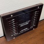
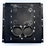
While I'm waiting for other parts and in an attempt to use extra parts from the NOS Threshold SA-1 restoration/upgrade project I posted about here, I purchased a 400a with blown 6A rail fuses. I've seen similar threads about this exact issue. It'll be something like "rail fuses blow immediately and LEDs on meter are all illuminated". Unfortunately, no one who takes these projects on really ever seems to post a conclusion or any kind of useful info. I'll try.
The amplifier came in yesterday, so I got to work and took the cover off. Immediately found a cracked emitter resistor and given the current consumption needed to blow the fuse I could reasonably guess the associated NPN was shorted. Unsoldered it, tested it with my Peak DCA75 and it was shorted. However, as it typically goes, I didn't stop there. I tested all of the CLASSA8 NPNs and found most of the β values were in the teens (15, 18, 19, etc) with the exception of the device connected to the 10 ohm resistor, which tested at 93. The SCA-75 has shown to be predictive of what my Tek 576 would trace.
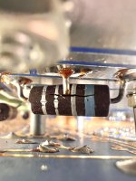
The big picture here is that the β is degraded because the transistors have likely slowly been destroyed by the conditions present in the circuit, so if you find one of your transistors has shorted, you likely need to replace all of them.
By the way, this 400A is really overbuilt and probably better than the later amps (which are still overkill mostly and easier to disassemble).
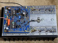
Now I'm waiting for new output transistors, and will rebuild the power supply in the meantime. I think I have the right capacitors.
The amplifier came in yesterday, so I got to work and took the cover off. Immediately found a cracked emitter resistor and given the current consumption needed to blow the fuse I could reasonably guess the associated NPN was shorted. Unsoldered it, tested it with my Peak DCA75 and it was shorted. However, as it typically goes, I didn't stop there. I tested all of the CLASSA8 NPNs and found most of the β values were in the teens (15, 18, 19, etc) with the exception of the device connected to the 10 ohm resistor, which tested at 93. The SCA-75 has shown to be predictive of what my Tek 576 would trace.

The big picture here is that the β is degraded because the transistors have likely slowly been destroyed by the conditions present in the circuit, so if you find one of your transistors has shorted, you likely need to replace all of them.
By the way, this 400A is really overbuilt and probably better than the later amps (which are still overkill mostly and easier to disassemble).

Now I'm waiting for new output transistors, and will rebuild the power supply in the meantime. I think I have the right capacitors.
Last edited:
Did some work on the PNP rail this afternoon. Removed as well as labeled all of the PNP transistors and also removed and replaced the emitter resistors on that side. I'll have to order more before I work on the left channel. Tested all of the transistors a few minutes ago and the β values were all over the place. There was one CLASSA6 at 15 and another at 263 (!) with the other values mostly scattered between 50 and 150. Of the eight on that side, five were CLASSA6 and three were 2N5476s with contemporary date codes and the same clear grease. Likely all of these are originals.
I think I'll put the outliers (which were all the CLASSA6 variety) on the Tek 576 and see what the heck is going on.
I'll also clean up the plate and the thinner portion of t-bar. I've found that 99.9% isopropyl alcohol takes the old greasy paste right off and it's as if it was never there afterward. I'm sure the weaker stuff probably works fine too. End result is so good I'm tempted to polish the aluminum, but I've resisted. The machining is very clean though.
Interesting, I have not seen such degradation in beta before. The devices were all selected for adequate beta.
I do have inventory of these if you can't find equivalents. They were 2n5878 and 76 parts.
I do have inventory of these if you can't find equivalents. They were 2n5878 and 76 parts.
Interesting, I have not seen such degradation in beta before. The devices were all selected for adequate beta.
I do have inventory of these if you can't find equivalents. They were 2n5878 and 76 parts.
That's very generous, thank you. I was able to find enough MJ15024G/25Gs to complete this channel's replacements. Seems they should work. I was able to get a pair of closely matched quad sets.
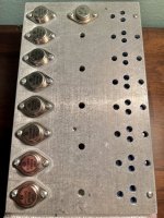
Arranged the lower β NPNs from each set toward what will be the middle of the heatsink since β should increase with higher temps (though I'm sure other factors offset this). The SA-1s even after I rebuilt them have slightly more heat toward the middle so I'm curious if this arrangement will make any difference when I pull out the Flir camera. For the left channel, I've ordered enough MJ15024G/25s to get eight matched closely. There was a low amount of variance overall with the 10 I had and I know it'd be fine just to install them without even worrying about β, but I think the experimentation is fun.
Cleaned up a little bit, but once I torque down the transistors, more thermal paste will get squeezed out so no point in getting them perfect right now.
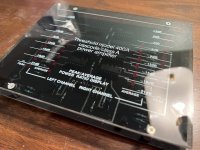
Tonight I also ordered my best guess of what the foam tape (or weatherstripping?) was that was originally between the faceplate and the the board. Also cleaned up the meter and can see the components on the board much more clearly now.
My method of polishing is time consuming but I've got practice and the results are worth it. I often feel the need to polish plastic screen or display filters on neglected vintage Tek and HP test equipment if I'm able to find one of the few models I'm interested in. Once you see the difference, it's hard not to. This is now bleeding over, but swirls are bad wherever they are.
Last edited:
One side of output transistors done. Timed myself and it took about 75 minutes to β match the MJ15025G PNPs, clean all of the of hardware including the original mica insulators, apply thermal paste to the back of each transistor as well as one side of each mica insulator (the opposite side from where you stuck it to the back of the PNP, obviously), then install the devices, and clean up the mess.

Time to inventory and then order driver board parts. I'm just going to repopulate them entirely given my feeling is that this amp was probably left on for an extended amount of time.

Time to inventory and then order driver board parts. I'm just going to repopulate them entirely given my feeling is that this amp was probably left on for an extended amount of time.
I notised that DCA-75 measured transistors as ok, but testing them in a cirquit some of them was shorted.
DCA-75 tests with to low current.
/Figge
DCA-75 tests with to low current.
/Figge
When I start seeing wide dispersions in β measured and emitter resistors that look like they have monkeypox, I just go ahead and replace the transistors, all of them along with the emitter resistors too. Clearly there is something wrong with one of these NPN output transistor measuring in the teens, just as something isn't right with a PNP output measuring at 263. Even if it isn't a dead short, problems already showing up in low current tests likely will only get worse in-circuit. To illustrate the difference in dispersion between old outputs and the MJs I just put in: The closest matched 8 of the 10 MJ15025G PNPs I had on hand all had β values of 78-83 or a range of 5. The originals had a range of nearly 250. There is no way that was the case in 1979 when these semiconductors were made and I wasn't even alive yet! So, to be clear, it wasn't even a consideration to keep the old ones in even if only one tested as a dead short when 3-4 other NPN outputs had a β under 20.I notised that DCA-75 measured transistors as ok, but testing them in a cirquit some of them was shorted.
DCA-75 tests with to low current.
/Figge
Last edited:
Found a decent copy of what I think is the schematic relevant to my unit.
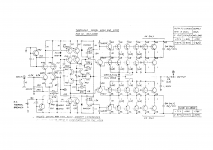
I'm getting my parts situation squared away and noticed the 300Ω resistor on the negative rail below the differential pair. According to the simulator, this is a suboptimal choice. There is a collector current imbalance and dc offset at the outputs in the differential pair if the schematic with this value is followed. If all else is equal and only that resistor is changed to 510Ω, the imbalance is almost completely resolved to the point of the dc offset is negligible. So the question is: what am I missing here?
Additionally, was there any reason why the bias pot wasn't placed between resistors? Seems like a prudent choice to limit adjustment.
Last edited:
The answer is: Who do you believe and trust, Nelson Pass or your simulator?So the question is: what am I missing here?
Loaded question.The answer is: Who do you believe and trust, Nelson Pass or your simulator?
I have found errors in these schematics before and Mr. Pass himself has said in the past they're not all completely correct. Simulators like the one I use weren't around back in the mid-70s when this amplifier was first made (were there even any at all?). Not exactly easy to check for errors in those days. Mr. Pass can correct me if I'm wrong about that.
For example, take a look at the above schematic and find the 5K bias pot. There's something missing...
So, it's not about belief or trust, really. Maybe the minor imbalance in collector current was a tradeoff that had to happen or maybe the simulator isn't interpreting something. It's also possible I didn't draw something correctly when I recreated the schematic.
If you were to ask me if I trusted the simulator though? I do. Paul Falstad who made CircuitJS1 (the simulator) also created this: https://en.wikipedia.org/wiki/Z_shell
Maybe you've heard of it.
In the end, I always do everything I can to make amplifiers I restore as reliable and also as finely tuned as possible. This isn't a business, I'm not Jon Soderberg or any other well-known audio tech. Each time I take on a project, I buy parts for that project and that project only which I make sure match my current inventory. This is why my finished boards don't look like a vomit of different colored and sized components as I've seen from various people who restore gear for a living. I don't mind spending the money to make things better where maybe from a business perspective it didn't make sense when these amplifiers were in production. I understand cost matters when running a business, I work at a hedge fund after all, but on a personal level, I generally don't want to blow fuses (or even have the chance) to blow fuses when adjusting bias and I do seek to eliminate 30 or 60 (and so on) mV of DC offset and I'll spend hours and hundreds of dollars to do it. Maybe I'll even get blue anodized transistor heatsinks to match the board they're on. Definitely always learn something new and in any case, it's better than staring at Excel.
Point is, I'm not asking these questions to be provocative or disrespectful which is why I made sure to say I'm likely the one "missing something".
Then you should follow your beliefs, this is DIY after all. Experiment, Nelson, I think, will be proud, he of all people say's this is entertainment. Just be sure to let us all know how it works out, you yourself said no one has followed up on this topic.
I really do not see the point of either one of your responses. It's as if you missed the first 7-8 posts I've made about this whole process.Then you should follow your beliefs, this is DIY after all. Experiment, Nelson, I think, will be proud, he of all people say's this is entertainment. Just be sure to let us all know how it works out, you yourself said no one has followed up on this topic.
Were you able to find the .68 Ohm wire wound emitter resistors? The wide first band, blue in this case, signifies a wire wound resistor in case you didn't know. Many people think these are Carbon Comp resistors. I sure wish I'd get some Thresholds in to work on, I've been repairing electronics for over 40 years and have yet to see a Threshold anything.🙁
Craig
Craig
Were you able to find the .68 Ohm wire wound emitter resistors? The wide first band, blue in this case, signifies a wire wound resistor in case you didn't know. Many people think these are Carbon Comp resistors. I sure wish I'd get some Thresholds in to work on, I've been repairing electronics for over 40 years and have yet to see a Threshold anything.🙁
Craig
I knew they were .68Ω and wire wound but I didn't realize what that blue band meant, that's good to know!
Anyway, I ended up using the extra 1Ω non-inductive wire wounds from the SA-1 project where I replaced all 80 of them. I had purchased 100 to get the quantity discount and figured I'd have a use for them and now I need even more. The positive here though is that once you've replaced 80 of them, 30 or so doesn't seem that bad.
Doing work on the drivers boards for these amps is slow work. The components are tightly placed, the boards are double sided, and the gold traces sometimes don't seem to want to take the solder. Very high quality and tough though so it doesn't make me discontent to work on them like I would be if they were ARC boards for example.
- Home
- Amplifiers
- Solid State
- Threshold 400a Blowing Rail Fuses w/ All LEDs illuminated
