Hi Andrew. I'm confused by the difference in the position of the two capacitors I mention in post 34?
Yes, the paths to appear to be close coupled. I'm a little confused about the location of the HBR.
-According to the article, it should not go to chassis ground, but to the star ground, correct?
-If I already have a lead from the star ground to the RCA barrel, would it even make sense to run another lead from the star to the HBR that is attached to the RCA barrel?
-I was thinking to put the HBR between the star ground and the RCA barrel but am worried since this acts as a ground for other areas of the PC board, this might not be a good idea. Try or don't try?
Thanks,
Eric
Your last pic confirms there is a mistake in the drawing.
The input RCA barrel is now confirmed as having a connection to Power Ground. That is necessary for the amplifier to work.
The existing connection via the 10r is an EXTRA connection.
Note the sch uses a different symbol. I think that "E" symbol is intended to be the Chassis/enclosure.
Back to the RCA barrel to Power Ground connection. This is the signal return current route.
It should be close coupled to the Signal Flow/Hot route into the amplifier input.
Is it?
Follow the two signal traces and check they are close coupled all the way from RCA to amp input.
It may be that with the cover removed continuity between heatsink and chassis has been lostIf I put my finger on the heat sink and my thumb on the chassis ground, the buzz is just about gone.
The only connection at the RCA socket should be the screened wire. The HBR should be in the signal return 0V connection to the power supplyI'm a little confused about the location of the HBR.
The only connection at the RCA socket should be the screened wire. The HBR should be in the signal return 0V connection to the power supply
Where should the ground that now goes to the screened wire on the RCA be attached? I need that ground for other circuitry on the FEB. Should I connect it where the screen attaches to the PC board?
(How do you edit posts here, I can't find a "button". I want to update the schematic to show the the ground on the RCA barrel)
Thanks,
Eric M.
Yes, if I understand correctly what you have marked "S" are only connected to the screen of the input wire, this is why there is that connection at the RCA barrel to the star, the connection should be from the amplifier input end on the PCB and this is where you can put the HBR.
There is a 30 minute time limit for editing
There is a 30 minute time limit for editing
Yes, if I understand correctly what you have marked "S" are only connected to the screen of the input wire, this is why there is that connection at the RCA barrel to the star, the connection should be from the amplifier input end on the PCB and this is where you can put the HBR.
Is this what your suggesting? (See attached drawing)
Attachments
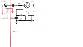
Yes, but move the resistor over to the board end too, take a wire from "S" via HBR to star ground
Yes, if I understand correctly what you have marked "S" are only connected to the screen of the input wire, this is why there is that connection at the RCA barrel to the star, the connection should be from the amplifier input end on the PCB and this is where you can put the HBR.
Or is this what you had in mind?
Attachments
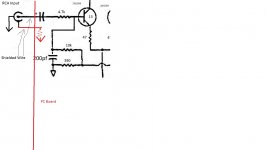
You are still showing a connection from the RCA to star, that shouldn't be there
How's this?
Attachments
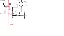
Yep, and what you show in red there will also include the other ground connections that you labelled "S". Can you see how that is now like the HBR signal ground connection in Bonsai's article?
OK, that makes sense. I was wondering where the "S" ground would tie in.
Is the detail attached correct now?
Is the detail attached correct now?
Yep, and what you show in red there will also include the other ground connections that you labelled "S". Can you see how that is now like the HBR signal ground connection in Bonsai's article?
Attachments
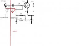
What I mean is you said that all the grounds marked "S" are connected to the screen, so all you need to do is take a wire from there via the resistor to the star, just ONE wire from that point
OK, yes, all the grounds marked "S" will attach to the star ground through the resistor in detail #3. So, back to detail #3. Is it OK that all the circuitry connecting to the grounds labeled "S" will now need to pass through the 10 ohm resistor?
Thanks,
Eric
Thanks,
Eric
What I mean is you said that all the grounds marked "S" are connected to the screen, so all you need to do is take a wire from there via the resistor to the star, just ONE wire from that point
I'm going to check all the resistors on the board (the only components I have not checked yet) and then reassemble and try again. I'll post up.
A question about the PC board and soldering. As I inspect the resistors and their installation, I notice some of the traces are on the top of the board and some are on the bottom. I have been doing all my soldering on the bottom. If I have a component with a trace on the top and just a solder pad on the bottom, do I need to make sure the solder flows through to the top of the board to make a good connection with the top trace or does the trace extend through the hole and connect the top and bottom traces already?
Thanks,
Eric M.
Yes, it should be fine as it's only the input stage ground
The holes are plated through, but if a component has been removed the through plating can be pulled out, so if in doubt check for continuity
I don't think that 10r is an HBRR/HBRL.Yes, the paths to appear to be close coupled. I'm a little confused about the location of the HBR.
-According to the article, it should not go to chassis ground, but to the star ground, correct?
-If I already have a lead from the star ground to the RCA barrel, would it even make sense to run another lead from the star to the HBR that is attached to the RCA barrel?
-I was thinking to put the HBR between the star ground and the RCA barrel but am worried since this acts as a ground for other areas of the PC board, this might not be a good idea. Try or don't try?
Thanks,
Eric
I think it is an attempt to connect the input barrel (exposed conductive part) to the Mains Protective Earth.
If I have guessed correctly, then it is very dangerous. The resistor when exposed to a mains fault on the RCA will burn out and may do this before the mains fuse has ruptured. (230Vac across a 10r resistor develops an average power dissipation of 5290Watts. But the 10r limits the Fault Current to 23Aac and the fuse may survive.)
If this is a PE to barrel Safety connection, then it needs a pair of inverse parallel Power Diodes to pass Fault Current and it's this that blows the mains fuse.
HBRR/HBRL is discussed at length in D.Joffe's paper.
Last edited:
Leach and Self suggest RCA barrel as the MAG to Chassis connection.It may be that with the cover removed continuity between heatsink and chassis has been lost
The only connection at the RCA socket should be the screened wire. The HBR should be in the signal return 0V connection to the power supply
Can the wiring to the RCA survive Fault Current?
- Status
- Not open for further replies.
- Home
- Amplifiers
- Pass Labs
- Threshold 4000 rebuilt - buzzing, need advice