You're welcome. Proper grounding is a fascinating subject, with many variables and not always easy to solve......
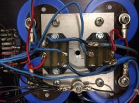
I wanted to point out the wiring I noticed on 3 of my Thresholds (2 working, 1 is the topic of the post).
The RCA is isolated from the chassis.
From the RCA common terminal there is a:
-wire running to ground star at capacitor plate
-shielded wire running to FEB
-10 ohm resistor grounding to chassis next to RCA jack (there is a wire at the bottom of the chassis connection the chassis to the ground star also).
Does any of that sound like a potential ground loop issue?
Also, I moved the ground star to the top, side of the aluminum plate (see picture). Was that not a wise idea?
Thanks,
Eric M.
Attachments
Last edited:
nope
Nope to "Does any of that sound like a potential ground loop issue?"
or
Nope to " I moved the ground star, was that not a wise idea?
I think you will find this useful, it's by member Bonsai http://hifisonix.com/wordpress/wp-c...re-up-a-Power-Amplifier_Updated-Autosaved.pdf
That was a fantastic article. I now see why that ground should not be there. Some of the more technical items at the beginning were over my head, but most of the ground loop issues and how to address them were clear.
Thanks again for the article.
I'll post up after removing the ground and testing. I need to put the left side back together (I got ahead of myself and pulled it apart).
Thanks,
Eric M.
So, I moved the ground star to exactly where it shouldn't be according to that article. Back to the center it goes. I wanted to keep the wires on top just for easier access or would it be better to keep them on the bottom to keep further away from supply lines?
probably.The RCA is isolated from the chassis.
From the RCA common terminal there is a:
-wire running to ground star at capacitor plate
-shielded wire running to FEB
-10 ohm resistor grounding to chassis next to RCA jack (there is a wire at the bottom of the chassis connection the chassis to the ground star also).
Does any of that sound like a potential ground loop issue?
Multiple wire from the signal input means there could be multiple routes for the signal current to flow around.
Repeat that for two channels and you have the potential for many LOOPS.
Good to know, thanks.
-I'm going to experiment with removing the one ground that goes to the ground star.
-I know the shield must remain and will leave that as is.
-I'm assuming the 10 ohm resistor is a "Hum Breaking Resistor" and should be left in place. Or should I experiment with removing that as well?
Eric M.
-I'm going to experiment with removing the one ground that goes to the ground star.
-I know the shield must remain and will leave that as is.
-I'm assuming the 10 ohm resistor is a "Hum Breaking Resistor" and should be left in place. Or should I experiment with removing that as well?
Eric M.
Hi, it depends where exactly it is, but it's probably an HBR 😉, they are often necessary when you have more than one channel. No harm experimenting though.
Hi, it depends where exactly it is, but it's probably an HBR 😉, they are often necessary when you have more than one channel. No harm experimenting though.
Hi Scott,
I reread the article you sent me. I have moved the center tap from the transformer secondary back to the center of the ground plate but kept all the signal grounds to the side (see picture). If I'm understanding the article, I think this is the correct configuration. The article only dealt with one bridge rectifier and 2 caps, I've got twice that.
I was also thinking that the HBRs should go to the ground star, not to the chassis as they are now. I might experiment with that as well.
Lastly, I will need to extend 2 of my grounds to reach the left channel FEB now that the ground star is to the right side of the plate. How important is it to keep all the grounds the same length? If two are 2" longer, should I replace all to match length?
Thanks again for the article, I can see it's going to be a reference tool from here on out. Also, loved the tip on using headphones. This was one of my issues when testing with tiny cheap speakers on my work bench, I couldn't hear the hum until I put the amp in my system.
Eric M.
Attachments
You could even create a kind of T for the signal grounds by making a star away from that large ground plate.
The HBRs should be in the signal return wire (screen),try without them first
The relative lengths of the wires doesn't matter, I'd be interested to know why there are two of them, it might be possible to improve on that but it would be necessary to see a circuit diagram if you can find/post one
The HBRs should be in the signal return wire (screen),try without them first
The relative lengths of the wires doesn't matter, I'd be interested to know why there are two of them, it might be possible to improve on that but it would be necessary to see a circuit diagram if you can find/post one
You could even create a kind of T for the signal grounds by making a star away from that large ground plate.
The HBRs should be in the signal return wire (screen),try without them first
The relative lengths of the wires doesn't matter, I'd be interested to know why there are two of them, it might be possible to improve on that but it would be necessary to see a circuit diagram if you can find/post one
I was thinking the same thing with the ground plate. Have another one cut with a "T" off to the back of the amp and do all my signal grounds there. If I can figure out my buzz issue first, I may do that.
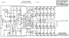
I have posted the schematic. I got it from someone here (Tony, I think?) I have updated it to represent my amp and labeled the substitute part#'s I used.
I have just finished experimenting with the right channel (the one that did not have as much buzz issue), The left channel FEB and output boards are out.
-#1 With wire REMOVED from ground star to common of RCA, shorting RCA plug in, headphones hooked to speaker out, no buzz. No buzz when wiggling ground wires.
-Same set up as #1 above, but remove shorting RCA plugs. A little buzz (not much, probably within tolerances). Wiggle ground wires, no buzz.
-Same set up as #1 except HBR connected to ground star (not to chassis next to RCA). Buzz increased. No buzz when wiggle ground wires.
-Same set up as #1 but removed HBR. Turned on amp and noticed meters went up to max. I'm assuming the buzz was 200 watts but didn't want to confirm with speakers. I hooked up the HBR and retested to make sure I didn't damage anything. All is OK.
I'm moving on the the problem channel, LEFT, and will post up.
Eric M.
Attachments
Can you confirm how the HBR is connected, one end to RCA and you've been moving the other end? Also try and identify where on the schematic the two black ground wires are connected
Can you confirm how the HBR is connected, one end to RCA and you've been moving the other end? Also try and identify where on the schematic the two black ground wires are connected
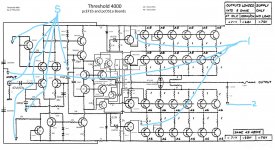
See the attached diagram for the location of the 2 grounds going to the FEB from the star ground.
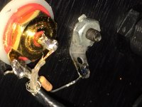
For the HBR, it solders to the same point as the shield (or screen) of the coax cable on the RCA and it connects to a lug that is screwed to the rear panel next to the RCA. (See the picture)
Thanks
Attachments
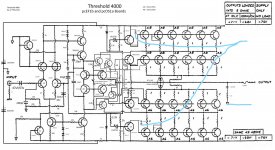
Are you sure that's a resistor? A capacitor is often used in that position.
Also the two capacitors that are connected to the ground wires on the schematic are in different relative positions, one is to the power rail, the other to the output transistors. Can you confirm this isn't a mistake on the diagram?
Also the two capacitors that are connected to the ground wires on the schematic are in different relative positions, one is to the power rail, the other to the output transistors. Can you confirm this isn't a mistake on the diagram?
Last edited:
Are you sure that's a resistor? A capacitor is often used in that position
Yes, I checked the parts as I replaced them. There was a 10 ohm resistor there before. Also, the other 4000 I have apart has the same resistor in that location.
Are you sure that's a resistor? A capacitor is often used in that position.
Also the two capacitors that are connected to the ground wires on the schematic are in different relative positions, one is to the power rail, the other to the output transistors. Can you confirm this isn't a mistake on the diagram?
Confirmed, this is not a mistake on the drawings.
Left channel tested, here is what I got:
-Still has buzz when RCA jack has nothing plugged in. It's almost as quiet as it should be (I think, this is the first time I've done with the headphone method) when the shorting RCA jacks are in or if plugged into a preamp.
-What I noticed this time is it isn't the ground wires getting moved that creates more of less buzzing, it my hand getting closer or touching or moving something inside. I can put my finger on one of the FEB transistor heat sinks and it gets much quieter. If I put my finger on the heat sink and my thumb on the chassis ground, the buzz is just about gone.
Could there be an HBR resistor on the FEB that is bad?
Any other thoughts?
Thanks,
Eric
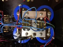
Here is an updated drawing showing where all the grounds lead to:
S = the trace on the PC board that the shield is soldered to. There is a ground wire leading from that connection on the RCA jack to the ground star
1 = a lead from the ground star to the PC board
2 = a second lead from the ground star to the PC board.
Neither S, 1 or 2 connect with traces on the PC board.
Does this help answer any questions?
Thanks,
Eric M.
Attachments
Your last pic confirms there is a mistake in the drawing.
The input RCA barrel is now confirmed as having a connection to Power Ground. That is necessary for the amplifier to work.
The existing connection via the 10r is an EXTRA connection.
Note the sch uses a different symbol. I think that "E" symbol is intended to be the Chassis/enclosure.
Back to the RCA barrel to Power Ground connection. This is the signal return current route.
It should be close coupled to the Signal Flow/Hot route into the amplifier input.
Is it?
Follow the two signal traces and check they are close coupled all the way from RCA to amp input.
Last edited:
- Status
- Not open for further replies.
- Home
- Amplifiers
- Pass Labs
- Threshold 4000 rebuilt - buzzing, need advice