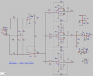
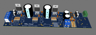
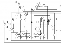
I have created this project to try how much power I can extract from LM1875 chip. At first I was thinking about having two in parallel, but then adding a third one was not too hard so I decided why not.
I have assembled two channels and measured them and they are performing very well.
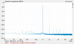
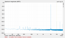
Producing 38.06W into 8 ohm resistor load.
THD+N at 1kHz is 0.0034%, and THD is 0.0028%.
Input signal connector footprint is for Neutrik NCJ6FA-H-0.
Edit: Simplified the gain structure by setting the gain to 10x (20x if you account for the balanced signal) and other minor fixes.
I have assembled two channels and measured them and they are performing very well.
Producing 38.06W into 8 ohm resistor load.
THD+N at 1kHz is 0.0034%, and THD is 0.0028%.
Input signal connector footprint is for Neutrik NCJ6FA-H-0.
Edit: Simplified the gain structure by setting the gain to 10x (20x if you account for the balanced signal) and other minor fixes.
Attachments
-
 Screen Shot 2023-03-03 at 9.38.04 PM.png47.1 KB · Views: 535
 -
 Screen Shot 2023-03-03 at 9.39.23 PM.png46.3 KB · Views: 454
 -
 Screen Shot 2023-03-03 at 9.37.20 PM.png72.2 KB · Views: 333
 -
 Screen Shot 2023-03-03 at 9.37.28 PM.png69.6 KB · Views: 448
 -
Gerber_PCB-lm1875-lm4562-rev2.0.zip156.3 KB · Views: 129
Last edited:

You may want to set up the gain stages such that they have unity gain at DC. That'll prevent them from amplifying the DC offset which, in turn, will minimize the amount of standing current in the ballast resistors. You can do that by adding coupling capacitors on the inputs to the differential amp sections.
Tom
Tom
I also wouldn't push the gain of the LM1875 below 20 dB (10 V/V). You have it at 19.6/3.9 = 5.0 V/V.
Tom
Tom
You may want to set up the gain stages such that they have unity gain at DC. That'll prevent them from amplifying the DC offset which, in turn, will minimize the amount of standing current in the ballast resistors. You can do that by adding coupling capacitors on the inputs to the differential amp sections.
Tom
Adding two film capacitors is an option, yes
How would I approach the process of measuring/determining the standing current? Should I disconnect current sharing resistors and measure each chip for offset voltage? Little confused on how to do it… Help me would be really appreciated.
I just want to quantify the problem - to understand the amount of impact standing current has on the amplifier operation.
Right now I mounted those chips on 150mm x 70mm x 40mm heatsink. It got pretty warm to touch when I tested 8 ohm load. I’m afraid it will get too hot if I start testing 4ohm load. Maybe fixing standing current issue will help to keep temperatures down.
I am assuming the addition of two differential signals should provide multiplication by 2. So only two (four) input transitions (Q3, Q4, Q5, Q6) inside the chip will see 5x , but the rest of the internal circuit will see 10x gain. Is this the right assumption?I also wouldn't push the gain of the LM1875 below 20 dB (10 V/V). You have it at 19.6/3.9 = 5.0 V/V.
Tom
Attachments
Last edited:
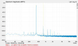
With this post I am attaching measurements' screenshots.
These results were obtained under the following conditions:
Load was 8 ohm 100W resistor
Power transformer was Antek AN-2222 with 22V-0V-22V secondary
Voltage after rectifying was 29.6VDC
Note that the voltage dropped to 28.6VDC under the full load
AC voltage at speaker output @400Hz sinewave was 17.45V @ THD+N of 0.0034%
Pout = sqrt(17.45)/8 = 38.06W rms
Note how the second harmonics is predominant on the graph. It suppose to result in warm sound, does it?
Attachments
Last edited:
No. Its the noise gain of the amps which matters for stability, not the signal gain.I am assuming the addition of two differential signals should provide multiplication by 2. So only two (four) input transitions (Q3, Q4, Q5, Q6) inside the chip will see 5x , but the rest of the internal circuit will see 10x gain. Is this the right assumption?
https://www.analog.com/en/analog-di...lifier,by the noise gain, not the signal gain.
In the link there is a formula for noise gain for the inverting and noninverting opamps. I wonder what is the formula for the difference amplifier?
The same formula works for the difference amp too seeing its a superposition of both, inverting and non-inverting.
No. The LM1875 'sees' a feedback network comprised of 19.6 kΩ and 3.9 kΩ and a voltage divider on its non-inverting input also comprised of a 19.6 kΩ and a 3.9 kΩ resistor. So from its perspective, it's configured for 19.6/3.9 = 5 V/V gain. Also keep in mind that the data sheet is for the entire chip, not subsections of it.I am assuming the addition of two differential signals should provide multiplication by 2. So only two (four) input transitions (Q3, Q4, Q5, Q6) inside the chip will see 5x , but the rest of the internal circuit will see 10x gain. Is this the right assumption?
Tom
Is it possible to put two Lm1875 in parallel simply by adding 0.22 ohms into the output?
https://www.diyaudio.com/community/...fication-to-current-drive.389985/post-7543404
It's a ready made stereo board - is paralleling possible?
Can I make like this a stereo board like this being a Mono amp?
https://www.diyaudio.com/community/...fication-to-current-drive.389985/post-7543404
It's a ready made stereo board - is paralleling possible?
Can I make like this a stereo board like this being a Mono amp?
Nice fun one.
Was on my bucket list
was gonna do 4 parallel 1875
But you did it though
And wow just wow.
Thought it was some oddity maybe
in sim.
When I tested it at lower frequency
100 Hz to 400 Hz
I got strong 2nd harmonic in sim as well
and wondered if it would really do that.
In real life. Always wanted to parallel 1875
for fun, and hear people freak out. lol
Absolutely hilarious
I always sim with series resistance
in the voltage sources and set
sample time close to frequency
being tested at.
Absolutely hilarious Tina gives
me exact number for 1875 at 400 Hz
good one man, how fun
YeahIs it possible to put two Lm1875 in parallel simply by adding 0.22 ohms into the output?
https://www.diyaudio.com/community/...fication-to-current-drive.389985/post-7543404
It's a ready made stereo board - is paralleling possible?
Can I make like this a stereo board like this being a Mono amp?
Lol, I should do four in parallel.Always wanted to parallel 1875
for fun, and hear people freak out. lol
The more the merrier!
It produced too much heat when I did three.
Also considering reducing gain to 5x and adding lead compensation capacitors, just so that ppl can freak out even more lol.
Bypassing feedback resistors with 33pF or 47pF should reduce Johnson noise and cancel out parasitic capacitances from invering pin to the ground.
Fun continues…
So paralleling is an option besides btl arrangement not only for 4 ohm operation. Where one chip is current limited.
I will try that out with the stereo amp board I have. It will be current driven.
I think the two paralleled channels need a Mono input signal so they add their power correctly.
I will try that out with the stereo amp board I have. It will be current driven.
I think the two paralleled channels need a Mono input signal so they add their power correctly.
- Home
- Amplifiers
- Chip Amps
- Three LM1875 in parallel producing 38W into 8ohm schematics and PCB