Hi there,
I was attemping to design a PCB for Rod elliott's state variable crossover, 2-way (i hope its ok posting as he doesn't offer this on pcb).
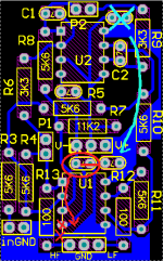
In this circuit you have 3 "grounds" which are the input, output and PSU. The PSU will be already properly filtered, so i just added 0.1uF between Vcc and Vdd pins and ground. I know the rule about .1uF between PSU op amps pins and GND, but, i had the feeling "where" those PSU currents would be flowing would alter the circuit.
1)In the image for example The red circled cap is put there so its the closest as posible to the psu GND because the trace aint that long to begin with. Otherwise the cap would decouple straight to in and and out GNDs. Should it be moved?
2)In the green circled cap the DC is decoupled to the extreme of the ground trace, and has to "go" by both amplifiers in the chip ground reference. The trace is long so its there (other wise Vcc is decoupled right before PSU GND).
3)Maybe if "as close as possible" is taken too far away, one of the negative rails decoupling caps could be omited?
4)If the PSU wasn't properly filtered, would something like 100uF need to be added?
Sorry about the numbered questions i just try to make the doubts clear, here is the image in that regard. I only know how to use the program regarding PCB design.
Best regards!
I was attemping to design a PCB for Rod elliott's state variable crossover, 2-way (i hope its ok posting as he doesn't offer this on pcb).
In this circuit you have 3 "grounds" which are the input, output and PSU. The PSU will be already properly filtered, so i just added 0.1uF between Vcc and Vdd pins and ground. I know the rule about .1uF between PSU op amps pins and GND, but, i had the feeling "where" those PSU currents would be flowing would alter the circuit.
1)In the image for example The red circled cap is put there so its the closest as posible to the psu GND because the trace aint that long to begin with. Otherwise the cap would decouple straight to in and and out GNDs. Should it be moved?
2)In the green circled cap the DC is decoupled to the extreme of the ground trace, and has to "go" by both amplifiers in the chip ground reference. The trace is long so its there (other wise Vcc is decoupled right before PSU GND).
3)Maybe if "as close as possible" is taken too far away, one of the negative rails decoupling caps could be omited?
4)If the PSU wasn't properly filtered, would something like 100uF need to be added?
Sorry about the numbered questions i just try to make the doubts clear, here is the image in that regard. I only know how to use the program regarding PCB design.
Best regards!
Attachments
Please provide a link to, or a copy of the schematic.
Why are you using only one PCB layer of copper?
Why are you using only one PCB layer of copper?
Rod’s state variable article. I think fig 2 is the relevant circuit. http://sound-au.com/articles/state-variable.htm
Its actually Figure 1 from this page:
https://sound-au.com/project148.htm
The reason for the board to be one sided is not based on anything, rather than it was fun to be more constrained.
https://sound-au.com/project148.htm
The reason for the board to be one sided is not based on anything, rather than it was fun to be more constrained.
You familiar with this? https://www.analog.com/media/en/technical-documentation/application-notes/AN-202.pdf
I see its pretty much the same circuit, tho the other blocks DC and has some resistrors and capacitors from the "unused" side of the potentiometer. I guess this are to block DC so the POTs dont make noise while changing value... Damn i feel i need those now..
I read it, its nice... but i understood SOME parts of it lol
What u take form Fig 3.b is that de decoupling cap should be as close to the load as possible, which would mean close to the GND output connection, since load will be in other equipment
I read it, its nice... but i understood SOME parts of it lol
What u take form Fig 3.b is that de decoupling cap should be as close to the load as possible, which would mean close to the GND output connection, since load will be in other equipment
Last edited:
The best question, as noted in the app note and in your first post, is: "where are those currents flowing?". Figure 9 represents a possible answer in the sense that it would be ideal to keep output currents away from input currents. Some authors have suggested keeping "signal ground" separate from “power ground” for this reason. What must be kept in mind is that PCB traces, power supply wires, and even full PCB ground planes, all have resistance and currents flowing through those resistances create a voltage. It is undesirable to allow the output current, or the current from decoupling caps, to impart a voltage across the return path for the audio signal as it will become part of the audio signal.

- Home
- Source & Line
- Analog Line Level
- Thougts about PCB grounds and decoupling