Very primitive. I dare say it may work after fiddling with the set up. Not for me, I prefer the old fashioned RCA designs.
!
for me it came from very good school😀😉
well designed, i to v vas, but unfortunately no degeneration resistors at the input and vfa😱 😉
... and bottom vas cascode zener should be in oposite direction, just shool mistake...
this one is cool too: http://web.archive.org/web/20010619234916/http://home.online.no/~tsandstr/a_strange_one.htm
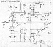
The School Amplifier from back in the day The School Amplifier
for me it came from very good school😀😉
well designed, i to v vas, but unfortunately no degeneration resistors at the input and vfa😱 😉
... and bottom vas cascode zener should be in oposite direction, just shool mistake...
this one is cool too: http://web.archive.org/web/20010619234916/http://home.online.no/~tsandstr/a_strange_one.htm
Last edited:
dual complementary jFET input feeding complementary folded cascode. Adventurous. I suspect workable, but I am not a designer.
Conventional double EF output stage.
You will probably have to reduce the 820r in the Vbe multiplier to get sufficient output bias voltage.
Three stability capacitors in the input, but none elsewhere.
Maybe more needed.
Can you simulate yet?
Conventional double EF output stage.
You will probably have to reduce the 820r in the Vbe multiplier to get sufficient output bias voltage.
Three stability capacitors in the input, but none elsewhere.
Maybe more needed.
Can you simulate yet?
@ padamiecki
That "cool" one looks better.
If you mean have i simmed this one = No
That "cool" one looks better.
Originally Posted by AndrewT
Can you simulate yet?
If you mean have i simmed this one = No
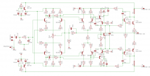
I have made very similar amp nearly year ago. It named BG4 (who knows maybe I will come back to it).
My knowledge was not sufficient to sort one problem, above 5kHz the clipp was very bad (now I know how to sort it out).
I really liked the sound of that amplifier but I didnt finished the project yet.
If you have some time and knowledge I can give you some of my measurements for reference.
My knowledge was not sufficient to sort one problem, above 5kHz the clipp was very bad (now I know how to sort it out).
I really liked the sound of that amplifier but I didnt finished the project yet.
If you have some time and knowledge I can give you some of my measurements for reference.
Attachments
Hi,
YMMV but IMO its over complicated for no useful purpose,
and has some dodgy features, not a good DIY amp IMO.
rgds, sreten.
YMMV but IMO its over complicated for no useful purpose,
and has some dodgy features, not a good DIY amp IMO.
rgds, sreten.
Last edited:
................Three stability capacitors in the input, but none elsewhere.
Maybe more needed.
Can you simulate yet?
I mean:...........If you mean have i simmed this one = No
are you able to carry out a simulation to allow you to investigate where additional stability components could be placed and what values might be workable in the built amplifier?
Last edited:
Would this be an early design by a (then student) Terge Sandstrom, employed in 1970s by Elektrocompaniet in Oslo? I found this reference for the schematic in your link: Electrocompaniet 'Electro' - Vintage - Pre/power amplifiers
Sandstrom went on to some heights as a designer but the parts specified in the schematic suggest he hadn't then understood the problems of mirror-image symmetry with such poor complements. The title "school amplifier" is probably apt.
Surely there have been improved designs along this line and also much better suited complements since the 1970s. Why not check later work?

- Home
- Amplifiers
- Solid State
- Thoughts on this Amp ?