the common coax is 75ohms characteristic impedance.
50ohms coax has a slightly higher capacitance if it's the same size as the 75ohms coax.
XLR often uses 100ohms or 110ohms characteristic impedance twisted pair for cabling. This may have less capacitance than either of the coaxials.
So lower capacitance helps XLR not phase shift. I'm not using coaxial, btw, if that matters for removing the shield. It's 3 connector. There's certainly no point in using coaxial wire on balanced outputs!
Last edited:
It's come to my attention that perhaps it's a harmonic issue, and not capacitance I'm experiencing.
I forgot to mention the 20k SMD stepped attenuator that doesn't have problems, is 10k higher in resistance than the Dale version that does!
It's quiet odd. I still think it's related to the ground relationship (in my head).
I forgot to mention the 20k SMD stepped attenuator that doesn't have problems, is 10k higher in resistance than the Dale version that does!
It's quiet odd. I still think it's related to the ground relationship (in my head).
What has XLR got to do with it?Destroyer OS. said:I see your point on how oscillations are easier. But I have to ask what makes them less of an issue for XLR?
If you have parasitic oscillation, as I suspect, then being "odd" is quite normal - RF is like that! It may depend on exact details of what you have attached and how you have connected it.It's come to my attention that perhaps it's a harmonic issue, and not capacitance I'm experiencing.
I forgot to mention the 20k SMD stepped attenuator that doesn't have problems, is 10k higher in resistance than the Dale version that does!
It's quiet odd. I still think it's related to the ground relationship (in my head).
At present we are all fumbling around in the dark, although some of us may be more in the dark than others. You still haven't shown us a picture.
I'm always in the dark..🙄..Its them virgin types and the full moon..😀At present we are all fumbling around in the dark, although some of us may be more in the dark than others.
Yes when is the photo shoot taking place?You still haven't shown us a picture.
 when will the evidence be complete?
  will it ever be solved...I know we will apply Qccam's Broom..
Then if all else fails the razor is the answer..
"when you have two competing theories that make exactly the same predictions, the simpler one is the better."
Stick some negative feedback on it..😀 or take the fuse out..if all else fails encapsulate the whole thing in six inches of lead..
remember to earth extraneous metalwork..
Regards
M. Gregg
Last edited:
All joking aside,
How is the earthing implemented..is it all to one star point?
NB if you use the lead it will give it a wow factor (WOW that's heavy) sorry 😀
Regards
M. Gregg
How is the earthing implemented..is it all to one star point?
NB if you use the lead it will give it a wow factor (WOW that's heavy) sorry 😀
Regards
M. Gregg
Last edited:
The amp isn't with me atm. I refered to XLR because it's balanced, like the output of this chip.
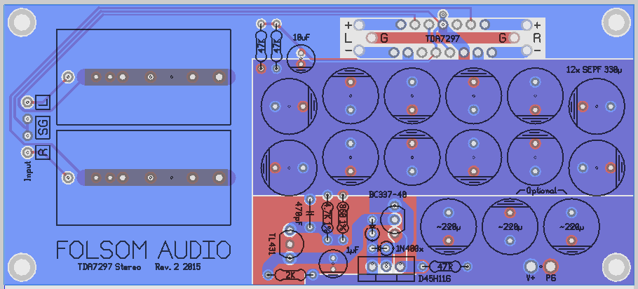
There's no earth. Here is the PCB. The Kmultiplier doesn't affect the problem. I am going to setup my old test one to check how much DC is between the input caps and chip, because electrolytics polarize in that position. The PDF diagram doesn't describe what's going on well.
There's no earth. Here is the PCB. The Kmultiplier doesn't affect the problem. I am going to setup my old test one to check how much DC is between the input caps and chip, because electrolytics polarize in that position. The PDF diagram doesn't describe what's going on well.
So mention of XLR was just some noise, to confuse us?
The picture won't open, for me.
Why has DC bias on electrolytics now cropped up. More confusing noise?
You really need to help us to help you. Otherwise we can't help.
The picture won't open, for me.
Why has DC bias on electrolytics now cropped up. More confusing noise?
You really need to help us to help you. Otherwise we can't help.
I'm not trying to confuse you. First I was trying to understand capacitance in relation to the speaker output, so I asked about why XLR works since both are balanced.
The electrolytics is something I remembered from over a year ago, so I thought I'd mention it.
I'm not sure why you can't see it, here's direct link http://www.audiocircle.com/image.php?id=120429
The electrolytics is something I remembered from over a year ago, so I thought I'd mention it.
I'm not sure why you can't see it, here's direct link http://www.audiocircle.com/image.php?id=120429


I think,
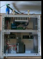
the photos everyone are waiting to see are of the actual amp wiring that you have built. So we can see what you have done and how you have connected it. Things like your grounding connections and the input wiring. Speaker wiring etc.🙂 Inside shots of the amp..
A shot of the input connections would be a good start showing the back of the input jacks and the input caps and position..
Regards
M. Gregg
Last edited:
The problem has existed within the current chassis, and when there was none. There's no secrets, two twisted pairs to the RCA, and DH Labs BL-1 to speaker terminals with shield wire only attached to amp pcb. Incoming power DC is two wires. (Can't post photo from phone, but cab later)
Everything is isolated from the chassis. It can optionally attach heatsink next to chip, to star ground (circuit). I don't think wiring has anything to do with the issue.
Everything is isolated from the chassis. It can optionally attach heatsink next to chip, to star ground (circuit). I don't think wiring has anything to do with the issue.
When you have parasitic oscillation then wiring details can sometimes be the only issue.
Get rid of the shielded output wire - you don't want to add extra capacitance here. Use shielded input wires. Why have shielding where it might do harm, and omit it where it does some good? Make sure input and output connections are well separated.
Get rid of the shielded output wire - you don't want to add extra capacitance here. Use shielded input wires. Why have shielding where it might do harm, and omit it where it does some good? Make sure input and output connections are well separated.
When you have parasitic oscillation then wiring details can sometimes be the only issue.
Get rid of the shielded output wire - you don't want to add extra capacitance here. Use shielded input wires. Why have shielding where it might do harm, and omit it where it does some good? Make sure input and output connections are well separated.
Thank you for suggestion, this may be good independently of the problem. But the original posting I don't believe to be subject to this at all given that it's existed independently of a shield.
They're separated, the input goes up and out, the output stays pretty level with PCB. It's as usual as any other amplifier that's nicely arranged.

Twisted AC to transformer (switch on hot), twisted to PSU, twisted to amp board that's got the same wiring as the PCB picture. The input wires are well above the output wires.
I've fired up my old one, and made sure there was not shielding of any kind. I've tried putting a few resistors inline and haven't found it to be causing as drastic of a change yet. But I've just started playing, so who knows just yet.
Last edited:
Unplug from mains.
Disconnect the Chassis to Audio connection.
Measure the resistance from Audio to Chassis. It should read open circuit.
Remake the Audio to Chassis connection.
Measure the L input socket to R input socket resistance. It should read near zero ohms.
Measure the L input socket to Chassis and the R input socket to Chassis.
These two readings should be well above 1r.
Come back with these 4 readings.
Had a look at the two vol pot diagrams in your Gallery.
Both are wrong.
The input signal is a two wire connection.
The two wires come to the two outer terminals of the vol pot.
The output signal is a two wire connection.
The two wires come from the wiper and the bottom/right terminals of the vol pot.
You MUST NOT use single wire connections to and from the vol pot.
It won't work.
Single wire connection BREAKS the CIRCUIT and Signal Current will not flow.
If however there is an inadvertent low impedance alternative route that completes the circuit, then Signal current will try to return via this "BAD" route and will certainly pick up interference. That will affect performance.
Unplug from mains.
Disconnect the Chassis to Audio connection.
Measure the resistance from Audio to Chassis. It should read open circuit.
Remake the Audio to Chassis connection.
Measure the L input socket to R input socket resistance. It should read near zero ohms.
Measure the L input socket to Chassis and the R input socket to Chassis.
These two readings should be well above 1r.
Come back with these 4 readings.
The ground on the input socket is tied to the other on the PCB, so yes, it's effectively 0. There's no connection to chassis, so it's way above 1R (I checked this before I even plugged it in).
What'ever you're referring to about the volume control, it's wired correctly and not part of the amplifier. RCA in, RCA out, it's perfect. Your discrepancy is with a 60 second drawing.
Last edited:
- Status
- Not open for further replies.
- Home
- Source & Line
- Analog Line Level
- Thoughts on reduction of 2nd order harmonic distortion