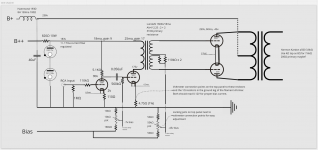
I inherited some spare parts, including a pair of Lundahl 1660s/18ma interstage transformers and the output transformers from an old Harman Kardon a500. I drew this design hoping to use those parts, plus gas regulator tubes because they look cool.
Will this even work? Forgive me, I don't really know what I am doing! (though I feel comfortable with electrical safety...)
Will this even work? Forgive me, I don't really know what I am doing! (though I feel comfortable with electrical safety...)
Attachments

Very impressive! When I just started this hobby, I could not make a design like this.
Some observations:
I think you have to put a resistor of 100K parallel to one of the two voltage regulators. Without this resistor they probably won't ignite.
Because you use tube rectification for B+, the voltage regulators will ignite while all the tubes are already conducting. So I think you going to hear them ignite through your speakers.
The half of the 5687 driving the interstage transformer would be dissipating 4.4 Watt, which is a bit higher than the maximum of 4.2 Watt in the datasheets.
The 110K grid stopper is unusualy high in value. The 1M grid resistor is also high but maybe you have a reason for that, like a preamp with highish output impedance.
The coupling capacitor of 0.056 uF seems too low to me, given the very low value of the anode resistor of the first stage.
I think it is better to be able to bias each 2A3 individualy. I also think that the resistors of 110K at the centre tap of the interstage transformer should not be there.
On the potentiometer you may want to have something that catches if the wipe presents an open circuit.
Do you even need the two 110K resistors at the interstage secondaries? I would add another pot so each 2A3's bias can be adjusted since you have split secondaries.
Oh wow, thanks so much for the feedback! I fixed the easy stuff - lowered the grid stopper/grid input - got rid of the 110k resistors - corrected that half of the 5687 to under 4.2 watts dissipation - and gave each 2a3 its own bias. I think the 0.056 uF cap is correct, but if not this is easy to fix later.
But yeah I guess I have the VR tubes all wrong 🙁 I want to use them because they are cool, do something useful, and are easy to understand. But the 5687 bias current will drop the voltage too low for them to ignite. Worse, I feel like if the wall AC voltage is very high/low and they have to absorb the difference then there might not be enough current left over for the swing needed by the 5687s?
I tried to use this resource but it was just too complex for me:
Tube Based Voltage Regulators - Part 5STEVE BENCH site mirror by JACMUSIC
I want to keep everything as simple as possible, while still using the VR tubes somehow... Is there any cheat I could use? Some slow-start relay? Or do I have no choice but to understand the above series? I have the original 7355 tubes from the harmon kardon a500, and I guess it would be cute to keep one on the amp.
Thanks again for all the help.
garbonzo666 wrote: "I want to keep everything as simple as possible, while still using the VR tubes somehow... Is there any cheat I could use?"
If you would 'sacrifice' the tube rectification than maybe yes (in the sense of: the VR tubes would already have ignited while the other tubes are not conducting yet) but than you would have to do some redesigning because the VR tubes can only pass 40 mA max. In your schematic they are passing 17 mA. When the 5687 is still warming up, there would be an additional 43 mA 'left' to take care of, so you would go way over the maximum of 40 mA.
Although this situation doesn't last long, I would think that it can damage the VR tubes. But probably other forum members can comment on this better than me.
Last edited:
On the potentiometer you may want to have something that catches if the wipe presents an open circuit.
I think that is why there is a 560K "Bias safety resistor" in the schematic of the power supply. But it's drawn like there is only one 560K resistor for all 4 bias pots. The wipers of these pots should ofcourse not be connected to eachother so I think that each wiper needs a seperate bias safety resistor.
Why the ridiculously high currents through the 5687? The first stage has a load of 5K Ohms - that's totally unnecessary and very non-linear. The second stage uses up most of the interstage transformer's BH linear-ish region, and for no reason. Just say no.
All good fortune,
Chris
All good fortune,
Chris
You may also want some mechanisms to balance the 2a3 pair and between channels.
In short every section/unit in a tube is never identical thus needs the ability to tune wrt the other sections in the circuit.
In short every section/unit in a tube is never identical thus needs the ability to tune wrt the other sections in the circuit.
This has already been advised in post #2 (and again in post #4...).
I need more coffee this morning..
Keep in mind SE to PP interstage transformers are somewhat hard to design and will be a main limiting factor. A common good practice is to place the phase splitting into the input, where requirements will be a lot less, then have a balanced input stage. If you wish, you can then have a PP to PP interstage, which is a piece of cake to design.
Push-pull 2A3 is for me still very close to the best sound that I have had, certainly good enough. I have some experience with two stage SE to PP grid drive, with the LL1660S and also a replacement. I am sure that you will find the LL1660S to be the limiting factor of the design.
...
What is your replacement ?
The primary inductance of 1660S/10mA is 42H .
1660S/18mA is roughly half of that.
Your suggestions are good ones.
Direct coupled the small signal tubes would be an improvement.
Will this even work? Forgive me, I don't really know what I am doing! (though I feel comfortable with electrical safety...)
I'm sure it'll work. It's very difficult to totally screw up a hollow state design. However, it could work a lot better.
1) Reduce the loading on the first 5687. From Frank's the rp for this type is 1.56K -- 3.0K. Triodes work best into light loads, so I'd shoot for an RP= 10K for the first VA. It's not driving a hard load here, so doesn't need to run so hot. As for the second stage (xfmr loaded) stick with fixed bias. The A Number One problem with cathode bias is that a bypassed cathode resistor can lead to leading currents (capacitive) that can resonate with the xfmr inductance to cause large distortions. Leaving the cathode resistor unbypassed drives up the effective rp that ruins low frequency response. Run the xfmr loaded stage hot to reduce rp to improve on low frequency performance.
2) You'd be better off using active voltage regulation for the front end, with the VR tube(s) providing the reference voltage. By running into a load of 43mA, you're inviting poofage should the load current drop too far. You're also compromising the life and accuracy of the VR tubes with high currents. Series connected VR tubes need balance resistors (100K -- 1M) to ensure the stray capacitance charges enough for both tubes to strike.
3) 40uF across hollow state diodes is way too much. Hollow state is low current/high voltage. Even though the 5U4GB boasts an Isurge= 1.0A/plate, that really isn't much considering the Isurge of 10A+ for even the small silicon power diodes. Capacitance only filters work with solid state diodes. For hollow state, you need to reduce that first filter capacitor to get the Isurge within spec, and use an RLC low pass filter to get rid of the ripple.
Thanks everyone for the great feedback. galac, I had no idea about max grid to ground resistance! And PFL200, I'm pretty embarrassed about the bias safety resistor error. Hopefully I would have caught that before soldering... Also thanks to Chris and Miles about the first half of the 5687 being improperly loaded. I'm not sure if I've fixed that well enough or not.
Generally the goal of the two 5687s is to have a very low output resistance for the 1660s (I've read this is important, and the whole design goal is basically "use these 1660s's"). So I picked a published operating point that has a low Rp. And then I only needed a bit more gain to work without a preamp so I used the other half of the 5687 to provide as little gain as possible...
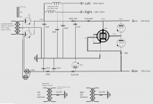
I spent a lot of time with the Steve Bench voltage regulator series and updated this design to use one of the 7355 pentodes from the donor Harman Kardon amp as a shunt regulator for the 5687s. If ya'll aren't tired of pointing out my dumb mistakes, I'd love to hear your thoughts on the updated design.
Generally the goal of the two 5687s is to have a very low output resistance for the 1660s (I've read this is important, and the whole design goal is basically "use these 1660s's"). So I picked a published operating point that has a low Rp. And then I only needed a bit more gain to work without a preamp so I used the other half of the 5687 to provide as little gain as possible...
I spent a lot of time with the Steve Bench voltage regulator series and updated this design to use one of the 7355 pentodes from the donor Harman Kardon amp as a shunt regulator for the 5687s. If ya'll aren't tired of pointing out my dumb mistakes, I'd love to hear your thoughts on the updated design.
Attachments

- Home
- Amplifiers
- Tubes / Valves
- Thoughts on newbie design for 2a3 pp with interstage phase splitter?