I am trying to get a handle on determining loadline and bias for power pentodes and I am not all that clear. I understand that for good linearity and power we want to to have the loadline cross at or slightly to the right of the knee in the 0V grid curve (is that correct?).
Given this power pentode. If we shoot for the knee it seems like a rather low value load of 3Kohms at 250V B+ (orange line) is what we need. Is that even close to right. Most lowish power pentodes such as EL84 seem to call for higher values like 5K which on this tube would seem to put the crossing point to the left of the knee at any reasonable bias point.
Please school me.")
Given this power pentode. If we shoot for the knee it seems like a rather low value load of 3Kohms at 250V B+ (orange line) is what we need. Is that even close to right. Most lowish power pentodes such as EL84 seem to call for higher values like 5K which on this tube would seem to put the crossing point to the left of the knee at any reasonable bias point.
Please school me.
Attachments
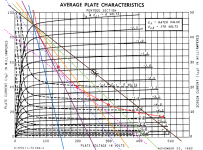
You will need to reduce the screen voltage to use the higher Z loadlines.
The other plate curve graph below gives the various screen V curves (for grid 1 = 0V, ie, the collection of top curves for the 1st graph)
So just draw the desired load Z line on the lower graph, and it will tell you what Vg2 to use. Then you can use the 1st graph with a proportionately reduced current scale taken from the 2nd graph knee intersection for the top graph 1 (Vg1 = 0) curve. The voltage steps on the 1st graph will also need re-scaling (due to the internal g2/g1 mu staying constant, ie if the knee Vg2 dropped 15%, then the Vg1 steps need to be dropped 15%)
Last edited:
- Status
- This old topic is closed. If you want to reopen this topic, contact a moderator using the "Report Post" button.