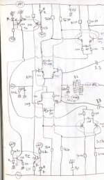
Otala's 1973 amplifier concept
If I am not missing something gross, the main feature or Otala's design is the lack of explicit dominant pole compensation. On the contrary there are several zeroes sprinkled here and there to make for better high frequency response.
This is compatible with low feedback factors, otherwise stability should be untamable.
This also determines in principle (it should be dissected carefully though) the OL transfer has not much to do with the classic Gilbert's gm/jwC thus doing away with the intrinsic quadrature nature of single dominant pole OpAmp topologies.
Performance figures as declared are unremarkable.
Rodolfo
Re: Re: Re: Re: Re: Re: Gain output stage
Tube_dude,
If I can be specific, the feedback signal is basically in phase with the input signal in the case you mention. (There is a small delta, depending on the amplifier transit time of course).
I think what you mean is that the output current is not in phase with the output voltage. But that is ALWAYS the case with complex loads, independent of the amp topology. It's an attribute of he load, not the amp.
Jan Didden
Tube_Dude said:
Hi Rudolfo
Because it has a High intrinsic open loop output impedance.
As the openloop output impedance is high , if you have a load with a phase shift (thats what you have with a speaker)the feedback will be not in phase wih the input signal,but with the phase of the load inprinted in it![snip]
Tube_dude,
If I can be specific, the feedback signal is basically in phase with the input signal in the case you mention. (There is a small delta, depending on the amplifier transit time of course).
I think what you mean is that the output current is not in phase with the output voltage. But that is ALWAYS the case with complex loads, independent of the amp topology. It's an attribute of he load, not the amp.
Jan Didden
lumanauw said:Hi, AndyC
Thanks for the offer. I still dont know which paper, since Otala writes about many topics.😀
Finally, I can get the Otala amp.
I tought the main issue to make good sounding amp is low OL gain, high OL bandwith and input stage that can take quite big voltage input.
Looking at the Otala amp, he uses 3 stages front stage (not the output stage yet). The first and second is differential, and the VAS is having current mirror.
How can this be called low OL gain?
Each stage is degenerated and they all work into resistive loads.
Depending on the values of the degeneration and load resistors,
the OLG could be relatively low and even unity!
I would have run the first stage at a higher current and omit
the second stage.
Cheers,
Terry
lumanauw said:I tought the main issue to make good sounding amp is low OL gain, high OL bandwith and input stage that can take quite big voltage input.
(...)
And I notice the output is using L-R. This is one indication of possible oscilation (typical of too high OL gain)
Actually, what is Otala's main thinking that some people considered as "the start" of good sounding audio amps? Low OL gain seems not the one. Or Otala is not about making good sounding amp, just advoiding TIM?
About the time Otala wrote his original article on TIM, there were some really bad sounding solid state amps being produced. He identified the TIM distortion mechanism, mainly with the idea that a necessary condition for getting a good-sounding amp is low TIM. Then he came up with the idea that to reduce TIM, one must have a low OL gain and a wide OL bandwidth. There turned out to be some errors in the paper, and several other AES guys pointed out that low TIM could be achieved with a large OL gain and narrow OL bandwidth. IOW, Otala's solution was sufficient to reduce TIM, but not necessary. This touched off a flame war in the AES journal that lasted for years. There is no known mathematical justification for the statement that to have low TIM distortion, one must have a low OL gain and a wide OL bandwidth.
But what about the design goal of having a "good sounding" amp? The problem is that there is really no consensus of how "good sounding" should be translated into engineering or mathematical terms. If the goal is to have a "good sounding" amp, then any design approach is just as good as any other, because the concept of "good sounding" is too vague from an engineering point of view. But from a marketing point of view, the story is a little different 🙂.
Regarding the L-R network, any feedback amplifier has the possibility of oscillation into capacitive loads. One problem is that an emitter follower by itself has a slightly inductive output impedance. When combined with a capacitive load, this can cause oscillations of the closed-loop amplifier. The higher the ft of the output transistor, the lower the output inductance of the emitter follower (without feedback), and the less sensitive it is to capacitive loads. But the output transistors that were available at the time Otala did his design had much lower ft than the ones available today like the MJL3281A. It wasn't until the higher ft BJTs became available (and power MOSFETs too) that the output inductor could be eliminated (unless of course the amp used no global feedback at all).
Geez this thread was going so well...
The recent fad attributing all sorts of mysterious audio defects that have escaped the poor ignorant “theoretically” oriented engineer (who obviously loads all of his amplifiers with pure resistors and only relies on purely linear systems theory) to this supposedly insightful, new paradigm of loudspeaker “back EMF” is alternately laughable and annoying to anyone willing to think a little about electromechanical system modeling. Back EMF is simply the coupling mechanism between cone/voice coil motion and the speaker’s electrical terminals, this couples the mass, spring and acoustic loading determined velocity of the coil to equivalent RLC electrical impedance representations – yes the transformed impedances are somewhat nonlinear and become complicated if you include cone modal vibrations/mechanical wave transmission/reflection/damping but engineers are used to dealing with uncertain device gains, phase shifts and loads. Good theoretical means for establishing the performance of feedback systems in the face of uncertainties within prescribed bounds are a standard part of the control engineer’s toolkit
Obviously a successful audio amplifier has to operate nearly linearly over the entire output V-I plane region that the complex and even somewhat nonlinear loudspeaker load requires. An output stage that has hard nonlinearities, such as dynamic or static deadzone in a poorly designed class B output is inherently flawed in itself, it makes no sense to blame “high negative feedback” for imperfectly cleaning up the errors. When all of the amplifier stages are well designed such that they are nearly linear under the actual operating conditions then linear systems theory can in fact tell us a lot about how feedback modifies the system’s output in light of the amplifier’s individual stage’s nonlinearities and any loading that stays within the weakly nonlinear operating limits.
Cherry, “Estimates of Nonlinear Distortion in Feedback Amplifiers” JAES V48#4 2000 shows how to use Bode’s sensitivity/Classical Feedback tools to give good #s on distortion
Cherry and Cambrell “Output Resistance and Intermodulation Distortion of Feedback Amplifiers” JAES V30#4 1982 shows feedback control of output stages with practical modeling complex impedance and nonlinear loads with a resistive load driven at both ends with differing test tones
Theil-Small parameters do help estimate the reflected impedance of dynamic drivers in the audio region but the results are simply not exciting/alarming; transformed mass-spring resonance results in an electrical terminal impedance peaks at the resonance frequencies – large impedance dips are more a function of crossover network choices than driver back EMF
A loudspeaker system couples the loads of multiple drives in different frequency ranges to the amplifier, the most nonlinear drivers are the lower frequency units that only see low input frequencies. Driver nonlinearities cause some higher order driver terminal currents (and much, much more IM in the excitation frequency band). Because of the reciprocal nature of the crossover coupling, low frequency driver nonlinear current products beyond their pass band are strongly attenuated at the amplifier terminals. Over the audio frequency band there is simply no distortion or stability consequence of driver load impedance within the linear operating region of the amplifier, typical SS amplifiers have output terminal impedance 100s-1000s of times lower than the loudspeaker. The tweeter’s nonlinear terminal currents do connect directly to the amplifier and very small components extend to 100 KHz – very small because tweeters are usually very linear, and because the actual nth harmonic distortion from a high nth order nonlinearity is so small with respect to the in band IM products from the high order nonlinearity (harmonic/IMD math has been presented many times in the audio world, Baxandall in WW, Czerwinski “Multitone Testing…” JAES V49#11 2001)
The largest dynamic driver nonlinear electrical variability is often increased voice coil resistance due to heating, voice coil electrical inductance also varies with position in the gap and pole piece eddy current cancellation effects modify the inductance, the high frequency model of a tweeter is dominated by the R – L components up to the coil resonance frequency from the coil’s inductance and adjacent turn parasitic C in the MHz – this causes an impedance peak which unloads the amplifier at the resonance frequency and then simply capacitively shorts the coil impedance above the resonance – typical cable capacitance is likely to be the dominant term at the amplifier end of the cable
Since there is some uncertainty in the high frequency region load impedance Zobel networks are still desirable but higher speed amplifiers can push up the frequency range where they need to decouple the amplifier from the load and have less influence on audio frequency impedance
andy_c said:
About the time Otala wrote his original article on TIM, there were some really bad sounding solid state amps being produced. He identified the TIM distortion mechanism, mainly with the idea that a necessary condition for getting a good-sounding amp is low TIM. Then he came up with the idea that to reduce TIM, one must have a low OL gain and a wide OL bandwidth. There turned out to be some errors in the paper, and several other AES guys pointed out that low TIM could be achieved with a large OL gain and narrow OL bandwidth. IOW, Otala's solution was sufficient to reduce TIM, but not necessary. This touched off a flame war in the AES journal that lasted for years. There is no known mathematical justification for the statement that to have low TIM distortion, one must have a low OL gain and a wide OL bandwidth.
So, what's the necessary condition to have low TIM?
The best online resource I've seen for this is here http://users.ece.gatech.edu/~mleach/lowtim/instage.html He assumes a voltage step input and computes the difference mode input to the amp under the assumption of linear operation (Figure 8). Then he chooses the emitter degeneration resistors in the input stage such that its linear range (Figure 7) isn't exceeded under these conditions. For two amplifiers with the same gain-bandwidth product, where one has high DC open-loop gain and narrow open-loop bandwidth, and the other the opposite, the waveforms of Figure 8 will be almost identical. The only difference will be that the steady-state value will be smaller for the unit with the high DC open-loop gain.
Rodolfo,
Pardon my late entry to this thread, but you are commenting on the Complementary Feedback Pair, sometimes called the Sziklai, after the Hungarian who discovered it in the States in the mid-fifties.
I have poor math ability, so will confine my comments entirely to the empirical. This is a most attractive topology, one which is very appealing to designers, and I've done a lot of bench testing. Here's the subjective results for a bipolar device driver and mosfet output, as you have drawn it.
1. Very prone to oscillation, particularly at Av = 1. This improves with Av of 3 or more.
2. Oscillation is always precipitated at crossover in low bias AB, and seems to be more of a problem on the negative rail.
3. Oscillation can be controlled with heavy Cdom from collector to base of the bipolar, but this seems to kill the vitality of the music stone dead. 220pF will do it.
4. In a PP Class AB, setting the bias is something of a thermonuclear trial, VERY tetchy. Bias setting is literally an accident waiting to happen.
5. The CFP works extremely well in a high bias, Class A situation, preferably single ended. I built an amplifier based around this topology eight years ago running 3A with a 50V supply (unity gain), and the linearity and transparency is extraordinary. The Zin is so high the base of the driver can be driven with a high rp tube (6SL7). Zout is 38 milliohms. I'm presently working on a bridged version of this SE amp with inductive loading (similar to the Zen 7) which hopefully will give power and glory.
To qualify the topology - yes, it works very well, but only in SE at high bias. In these circumstances it is extremely well behaved, with distortion all H2/H3 and measuring around 0.05% at full power. Collector loading of the driver is an issue.
Cheers,
Hugh
Hi, Terry Demol,
Yes, you are right. I never tought of that😀
It reminds me of a question I've been holding for so long. I saw this double differential in another commercial amp (attached), also in Kaneda amp.
If I need differential gain of 100X, what is the difference between doing it with a single differential 100X gain, compared with 2 series differential, each have 10X gain? The double differential will add more component, but some does it this way. What's the excel?
Hi, JCX,
I also interested in this Back EMF issue (like Graham Maynard said). I think this is more important than some think to sonic result of audio power amp (global feedback class AB amp). Is it because this is too difficult to measure, that people are pretending it dont exist/dont important? My simple DIY experiment (including/excluding output stage from feedback loop) shows that this is important, at least I can hear the difference.
Hi, Andy C,
Sorry, if I wrote wrong. I am not good with math and cannot follow those papers. The ones I can understand is Barrie Gilbert and Walt Jung (those with minimal math equations), but tell important thing about OpAmp designs.
Hi, AKSA,
Will those flaws of CFP still holds for reversed (mosfet for driver, bipolars for finals)? I'm thinking of this reversed type, cause it can block induction loading from final stage to VAS due of mosfet driver.
Yes, you are right. I never tought of that😀
It reminds me of a question I've been holding for so long. I saw this double differential in another commercial amp (attached), also in Kaneda amp.
If I need differential gain of 100X, what is the difference between doing it with a single differential 100X gain, compared with 2 series differential, each have 10X gain? The double differential will add more component, but some does it this way. What's the excel?
Hi, JCX,
I also interested in this Back EMF issue (like Graham Maynard said). I think this is more important than some think to sonic result of audio power amp (global feedback class AB amp). Is it because this is too difficult to measure, that people are pretending it dont exist/dont important? My simple DIY experiment (including/excluding output stage from feedback loop) shows that this is important, at least I can hear the difference.
See..... it is important 😀.(unless of course the amp used no global feedback at all).
Hi, Andy C,
Sorry, if I wrote wrong. I am not good with math and cannot follow those papers. The ones I can understand is Barrie Gilbert and Walt Jung (those with minimal math equations), but tell important thing about OpAmp designs.
Hi, AKSA,
Will those flaws of CFP still holds for reversed (mosfet for driver, bipolars for finals)? I'm thinking of this reversed type, cause it can block induction loading from final stage to VAS due of mosfet driver.
Attachments
lumanauw said:See..... it is important .(unless of course the amp used no global feedback at all).
Hi lumanauw,
I was referring to stability issues due to capacitive loads like what might occur with an electrostatic speaker. In other words, an impedance that's very low at frequencies in the hundreds of kHz and nearly 90 degrees lagging. When the back EMF of a conventional speaker becomes large, this is near resonance in the audio band where the impedance becomes large. A high impedance shouldn't be a problem for a well designed solid state amplifier.
Of course, if there's no global feedback, there's not much in the way of stability issues to consider, except the possible local VHF oscillation problem dealt with by the Zobel network.
Regarding the back EMF red herring, my view is best stated by quoting Self, who refers to "...the sadly uncritical way in which people accept an unsupported assertion as the truth simply because it is asserted with frequency and conviction."
Also, being able to hear the difference in amplifier sound with the output stage inside and outside the feedback loop is very different from being able to say with certainty the cause of that difference. That's a harder problem.
andy_c said:The best online resource I've seen for this is here http://users.ece.gatech.edu/~mleach/lowtim/instage.html He assumes a voltage step input and computes the difference mode input to the amp under the assumption of linear operation (Figure 8). Then he chooses the emitter degeneration resistors in the input stage such that its linear range (Figure 7) isn't exceeded under these conditions. For two amplifiers with the same gain-bandwidth product, where one has high DC open-loop gain and narrow open-loop bandwidth, and the other the opposite, the waveforms of Figure 8 will be almost identical. The only difference will be that the steady-state value will be smaller for the unit with the high DC open-loop gain.
So, the only required condition is to prevent the input stage from slewing?
That's absolutely right. The amp that I tested is cold amp (low biased AB). I suspect 2 things. One is back EMF (that is fedback to differential) or crossover distortion. I still dont know which.Also, being able to hear the difference in amplifier sound with the output stage inside and outside the feedback loop is very different from being able to say with certainty the cause of that difference. That's a harder problem
andy_c said:*snip*
Also, being able to hear the difference in amplifier sound with the output stage inside and outside the feedback loop is very different from being able to say with certainty the cause of that difference. That's a harder problem. [/B]
Thanks Andy for saying that!
et al,
I don't really yet grasp the thing why the speaker EMF should be any greater problem with a well designed SS amp.
Anyhow i try to learn and understand what eventual mechanism could ly behind this issue.
Anyhow at the moment I would say just that the feedback node does NOT know if the distorted signal is depending on the forward non-linearity in the amp or because of the so called speaker EMF as long as we ar talking about reasonably frequency range which is within the power bandwith (which could be let say 100 kHz or so..)... so at least so far I think there must be other issues "more" sensitive to the speaker EMF.
About making listening tests with an amp were we can swich between global an non global feedback I tend to say the same thing commented by Andy, BUT I see actually an intersting chance for the Altman SPLIF topology to be a suitable candidate with which we could perfom a test and evaluate how the NFB would be affected by the speaker EMF.
I actually think that if we take any speaker, it has of course not a straight impedance curve, BUT this can be corrected with an impedance correcting network, like the zobel network used to be used in speakers we just make it working over the whole audio range and beyond.
Because it's absolutely possible to get a fairly resistive impedance over the audio range for a speaker, I think the Altman SPLIF could be used for this kind of tests.
The Altman SPLIF topology was quite intensly discussed for some month ago, were I opposed against it to work as intended because among other reasons the sound will no doubtly be collored with a speaker that has an impedance curve that goes up and down along the audio range.
They SPLIF thread came up to alive at post
#343 .
Any comments?
Cheers! 😉
lumanauw said:Hi, Terry Demol,
Yes, you are right. I never tought of that😀
It reminds me of a question I've been holding for so long. I saw this double differential in another commercial amp (attached), also in Kaneda amp.
If I need differential gain of 100X, what is the difference between doing it with a single differential 100X gain, compared with 2 series differential, each have 10X gain? The double differential will add more component, but some does it this way. What's the excel?
By sharing the gain between 2 stages you can theoretically
get lower distortion if it is done correctly. However if the
degeneration is optimised between 2 stages for lower
distortion, all other things being equal, their will be a bit more
noise .
Cheers,
Terry
AKSA said:Rodolfo,
Pardon my late entry to this thread, but you are commenting on the Complementary Feedback Pair, sometimes called the Sziklai, after the Hungarian who discovered it in the States in the mid-fifties.
I have poor math ability, so will confine my comments entirely to the empirical. This is a most attractive topology, one which is very appealing to designers, and I've done a lot of bench testing. Here's the subjective results for a bipolar device driver and mosfet output, as you have drawn it.
1. Very prone to oscillation, particularly at Av = 1. This improves with Av of 3 or more.
2. Oscillation is always precipitated at crossover in low bias AB, and seems to be more of a problem on the negative rail.
3. Oscillation can be controlled with heavy Cdom from collector to base of the bipolar, but this seems to kill the vitality of the music stone dead. 220pF will do it.
4. In a PP Class AB, setting the bias is something of a thermonuclear trial, VERY tetchy. Bias setting is literally an accident waiting to happen.
5. The CFP works extremely well in a high bias, Class A situation, preferably single ended. I built an amplifier based around this topology eight years ago running 3A with a 50V supply (unity gain), and the linearity and transparency is extraordinary. The Zin is so high the base of the driver can be driven with a high rp tube (6SL7). Zout is 38 milliohms. I'm presently working on a bridged version of this SE amp with inductive loading (similar to the Zen 7) which hopefully will give power and glory.
To qualify the topology - yes, it works very well, but only in SE at high bias. In these circumstances it is extremely well behaved, with distortion all H2/H3 and measuring around 0.05% at full power. Collector loading of the driver is an issue.
Cheers,
Hugh
Gedday Hugh,
This latest beast sounds very tasty 🙂
WRT CFP FET/BJT, how does it handle capacitive loads?
Does it require a zobel or OP inductor?
I am deep deep in development trying to get a good OP stage
that is stable into for example a 2uF cap load without any
OP network but that is very linear.
It aint easy but there is light at end of tunnel.
And then theres just a plain vanilla BJT follower OP, sans
feedback, and with enough bias current I am shocked how
good it sounds, regardless of the significant harmonic
spectrum. Maybe Charles H. DID have it all figured out 🙂
Cheers,
Terry
AKSA said:Rodolfo,
Pardon my late entry to this thread, but you are commenting on the Complementary Feedback Pair, sometimes called the Sziklai, after the Hungarian who discovered it in the States in the mid-fifties.
.........................
Cheers,
Hugh
Hi Hugh:
Thank you very much for the valuable feedback from someone with direct working experience in this particular topology!
I might say I'm surprised with your concerns regarding bias, I built once a bipolar version with BD139-140 and TIP-41-42 if I remember well and had no problems on this department (this was about 15 years back). Yet if the prototypes I am building right now with MOSFET power stages turn into flames, I've been warned!
Rodolfo
Re: Geez this thread was going so well...
Glad to see you jumping in jcx!
And yes, I agree, in fact I pointed out the EMF nature in the SPLIF thread some time back though it looks it was not much taken into account.
The suggestion to include the T-S model in simulations is not a cure all either, but a (small) step forward from an ideal resistor. In fact the power conversion equivalent EMF could be made frequency dependent and slaved to the output current, I'd rather leave this to driver experts to figure out, something I certainly am not.
Neither I think it healthy to dismiss experiences based on shaky or plainly wrong reasoning - like the SPLIF concept itself - as long as the actual experimental results have a honest component of evidence, that is if we deem the reports credible.
It may signal there is something that escaped previous consideration and is worth checking independently to see what it is if there is really something.
Rodolfo
jcx said:The recent fad attributing all sorts of mysterious audio defects that have escaped the poor ignorant “theoretically” oriented engineer (who obviously loads all of his amplifiers with pure resistors and only relies on purely linear systems theory) to this supposedly insightful, new paradigm of loudspeaker “back EMF” is alternately laughable and annoying to anyone willing to think a little about electromechanical system modeling. .......
Glad to see you jumping in jcx!
And yes, I agree, in fact I pointed out the EMF nature in the SPLIF thread some time back though it looks it was not much taken into account.
The suggestion to include the T-S model in simulations is not a cure all either, but a (small) step forward from an ideal resistor. In fact the power conversion equivalent EMF could be made frequency dependent and slaved to the output current, I'd rather leave this to driver experts to figure out, something I certainly am not.
Neither I think it healthy to dismiss experiences based on shaky or plainly wrong reasoning - like the SPLIF concept itself - as long as the actual experimental results have a honest component of evidence, that is if we deem the reports credible.
It may signal there is something that escaped previous consideration and is worth checking independently to see what it is if there is really something.
Rodolfo
Ultima Thule said:
That's an interesting thread. Now that I'm up to speed on SPLIF technology, the next step is to learn more about BONG technology

I think it's not about using SPLIF or not, but about including/excluding output stage from feedback loop. SPLIF can do this, but taking the feedback from VAS also do this (without extra output stage).
The difference is heard with actual experiment, dont need measurement meters to know the difference (maybe measuring them will give opposite result from audible test)
Charles Hansen knows about this, he insisted making things non-global feedback (on everything?)
John Curl, although his commercial works uses global feedback (due to specification needed), I once read here that he actually likes the non-feedback, if everything was equal. He make an "non-feedback" experimental preamp now with CTC, trying to get a good measurement figures also from non-feedback type cct.
Nelson Pass, also does class AB power amp with excluding feedback from feedback loop. Look at his (later series) Threshold amps, or the currently Xamp series from Passlabs. Those take feedback from VAS, excluding the output stage.
The issue is known very well, but what really makes different sound in including/excluding output stage in classAB power amp?
Excluding output stage in classAB power amp will give worse measurement, worse damping factor. But why it sounds better?
OP amps, AM-to-PM
Hi lumanauw,
Sorry for taking so long.
You've got some excellent questions there and they made me dig into the Gilbert paper a bit more. He's basically using a simplified model of a 741 type OP amp, he does a lot of analysis to show that it produces a lot of distortion at 1/100 of Ft when asked to produce a 10V sine wave out. This should be taught and reinforced in any class that bothers to cover real world considerations for OP amps. You probably know that the simple OP amp theory that makes them easy to use goes something like this:
The OP amp has incredible differential gain and if any reasonable feedback is put around it, the output will do whatever it has to, to drive the differential voltage to zero. In the limit as a good approximation we say that the OP amp has infinite gain, thus if there was any differential voltage the output would blow up. The 741 has a gain of 200,000X at low frequencies *but* it uses dominant pole compensation meaning the that gain drops at 20 dB/decade reaching unity gain (Ft) at about 1 MHz. Unity gain is far away from 200,000X or the approximation of infinity.
A good tutorial will tell you that you better be 3 or 4 decades below Ft for the approximation of infinite gain to be a good one and the simple analysis to apply. Good designers will analyze the circuit for finite gain and can then use them judiciously closer to Ft.
Another consideration is that one should calculate the finite differential voltage for the required output. If you need 10V two decades (1/100) below Ft, you'll only have 40 dB of gain or 100X, thus the differential input voltage will be 10/100 or 100 mV. There will be significant distortion since this voltage is much more than 20 mV for this class of OP amp that does not include linearization of the diff amp. The very interesting point is his observation and analysis of the AM-to-PM effect. I had several professors point out, at least the frequency dependent non-linearity many years ago. RF and video guys study and usually know about these things.
We also know from practice that OP amps with 10 MHz Ft work well in demanding audio applications. This is not surprising when you consider how far away unity gain or one is from infinity.
He's not assuming open loop as you can see from his gain equation, he used a closed loop gain of 10.
About assuming a perfect sinusoidal output, sometimes it's reasonable to assume that a certain node voltage is a particular value, then work backwards to determine if the system will provide it. If the calculated distortion is say below 1%, that is not very different than 0, and the approximation was 99% correct. Note also that he was only analyzing one distortion mechanism, probably the worst one, but that from it he found this interesting AM-to-PM distortion.
lumanauw said:PB2, thanks for the papers. I cannot open the Otala's "ultimate HiFi" amp. http://home.online.no/~tsandstr/Ota... original.htm
Could you send it also?
After reading them (I dont understand the mathematics part) it seems they are talking about input stage nonlinearity (BJT especially) that contributes the most to the distortions fo the whole amplifier.
This is what I got after reading them (as DIYer)
Barrie G in his "Hawaii" article, writes an interesting approach. If the output is perfectly sinusoidal, what kind of input needed to make the output like that. Problem arises with BJT differential, because it takes very little change (20mV) to make 20V full sinusoidal in output. And that 20mV signal could be not sinusoidal to make the output good sinusoidal. This means the whole amp is not linear, because what is in to the amp is different shape to what happens from the output. This is with OL mode.
Hi lumanauw,
Sorry for taking so long.
You've got some excellent questions there and they made me dig into the Gilbert paper a bit more. He's basically using a simplified model of a 741 type OP amp, he does a lot of analysis to show that it produces a lot of distortion at 1/100 of Ft when asked to produce a 10V sine wave out. This should be taught and reinforced in any class that bothers to cover real world considerations for OP amps. You probably know that the simple OP amp theory that makes them easy to use goes something like this:
The OP amp has incredible differential gain and if any reasonable feedback is put around it, the output will do whatever it has to, to drive the differential voltage to zero. In the limit as a good approximation we say that the OP amp has infinite gain, thus if there was any differential voltage the output would blow up. The 741 has a gain of 200,000X at low frequencies *but* it uses dominant pole compensation meaning the that gain drops at 20 dB/decade reaching unity gain (Ft) at about 1 MHz. Unity gain is far away from 200,000X or the approximation of infinity.
A good tutorial will tell you that you better be 3 or 4 decades below Ft for the approximation of infinite gain to be a good one and the simple analysis to apply. Good designers will analyze the circuit for finite gain and can then use them judiciously closer to Ft.
Another consideration is that one should calculate the finite differential voltage for the required output. If you need 10V two decades (1/100) below Ft, you'll only have 40 dB of gain or 100X, thus the differential input voltage will be 10/100 or 100 mV. There will be significant distortion since this voltage is much more than 20 mV for this class of OP amp that does not include linearization of the diff amp. The very interesting point is his observation and analysis of the AM-to-PM effect. I had several professors point out, at least the frequency dependent non-linearity many years ago. RF and video guys study and usually know about these things.
We also know from practice that OP amps with 10 MHz Ft work well in demanding audio applications. This is not surprising when you consider how far away unity gain or one is from infinity.
He's not assuming open loop as you can see from his gain equation, he used a closed loop gain of 10.
About assuming a perfect sinusoidal output, sometimes it's reasonable to assume that a certain node voltage is a particular value, then work backwards to determine if the system will provide it. If the calculated distortion is say below 1%, that is not very different than 0, and the approximation was 99% correct. Note also that he was only analyzing one distortion mechanism, probably the worst one, but that from it he found this interesting AM-to-PM distortion.
- Status
- Not open for further replies.
- Home
- Amplifiers
- Solid State
- Thoughts Concerning Cordell, Otala, and Gilbert papers