Hi,
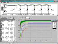
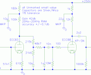
I have question regarding Thorsten's DC phono PSU (Please see the attached schematic)
Previously I use a tube regulated PSU to go with thorten's DC phono and there's no hum at all.
A few days ago I changed the PSU to the recommended PSU for the phono by Thorsten which is a simple 5 stage RC PSU. I did run the PSU schematic in PSUD II to see how much ripple left at the end stage and saw that it should be less than 1mv which is good.
However when I install the new PSU to my phono preamp I heard rather loud hum from my speaker (92db sensitivity). I used my Fluke 77 multimeter to check and see that I got about 4.4mv of AC ripple, that's why I heard a loud hum. I did some measurement as follow:
- The AC ripple at the first capacitor: ~4.7v
- The AC ripple at the second capacitor: ~100mv
- The AC ripple at the third capacitor: ~15mv
- The AC ripple at the fourth capacitor: ~4mv
- The AC ripple at the fifth capacitor: ~4.4mv
- The AC ripple at the sixth capacitor: ~4.7mv
The result came as a big surprise to me as it does not match with the PSU II simulation and I don't know why from the third RC stage to the fifth RC stage the ripple does not seem to go down instead go up???
Does anyone know why?
Attachments
What are those results if you, in stead of connecting the amplifier, just connect a 10W 8k2 dummy resistor as a load to that supply circuit?
Hi,
I have question regarding Thorsten's DC phono PSU (Please see the attached schematic)
Previously I use a tube regulated PSU to go with thorten's DC phono and there's no hum at all.
A few days ago I changed the PSU to the recommended PSU for the phono by Thorsten which is a simple 5 stage RC PSU. I did run the PSU schematic in PSUD II to see how much ripple left at the end stage and saw that it should be less than 1mv which is good.
However when I install the new PSU to my phono preamp I heard rather loud hum from my speaker (92db sensitivity). I used my Fluke 77 multimeter to check and see that I got about 4.4mv of AC ripple, that's why I heard a loud hum. I did some measurement as follow:
- The AC ripple at the first capacitor: ~4.7v
- The AC ripple at the second capacitor: ~100mv
- The AC ripple at the third capacitor: ~15mv
- The AC ripple at the fourth capacitor: ~4mv
- The AC ripple at the fifth capacitor: ~4.4mv
- The AC ripple at the sixth capacitor: ~4.7mv
The result came as a big surprise to me as it does not match with the PSU II simulation and I don't know why from the third RC stage to the fifth RC stage the ripple does not seem to go down instead go up???
Does anyone know why?
Did you measure that 3rd and 4th ripple directly across the caps or from the top of the cap to some other ground point?
You probably would measure he expected levels directly on the cap.
Then we should look at your grounding system as you may have extra hum because of some ground loop in the supply system.
Also, if you connect both meter leads to the top of the last cap, do you measure (close to) zero?
Jan
Last edited:
Jan,
"Did you measure that 3rd and 4th ripple directly across the caps or from the top of the cap to some other ground point?"
I think he MUST have done those measurements directly across those caps.
To replace the amp with a simple dummy load directly across the output terminals
will supply info if your suggestions are the root cause of the problems I think.
Last edited:
Joe, I don't know, often measurements are done against a convenient ground point, which may or may not have any amount or ground loop ripple. Better to be sure.
I also don't know what a measurement with a dummy load might tell me. What's your reasoning here?
Jan
I also don't know what a measurement with a dummy load might tell me. What's your reasoning here?
Jan
Just to get more info about things you are correctly asking
ncc.
I want to be certain that nothing is interfering/interacting between that new supply and the amplifier.
Also your question to him:
"Also, if you connect both meter leads to the top of the last cap, do you measure (close to) zero?"
is quite to the point, hope he will answer that one too!
ncc.
I want to be certain that nothing is interfering/interacting between that new supply and the amplifier.
Also your question to him:
"Also, if you connect both meter leads to the top of the last cap, do you measure (close to) zero?"
is quite to the point, hope he will answer that one too!
I think gut feeling-like unreasoned suggestions only detract from the ongoing discussion/thought flow. Nothing to do with what I asked about.
Jan
Jan
Hi Jan and Joe,
Thanks for answering my question.
Jan,
I measured that 3rd and 4th ripple directly across the caps. When I measured the last cap, the ripple is about 4,7mv that's why it make me wonder how can that be?
Joe,
Yes, I did connect a 10K WW resistor as load
At the beginning, I had some suspicion that the power transformer may inject some hum into the circuit although it's about 15cm from the power supply. I tried to move the transformer further away and even turned it 90 degree with no change in ripple result on the last capacitor.
Thanks for answering my question.
Did you measure that 3rd and 4th ripple directly across the caps or from the top of the cap to some other ground point?
..............
Also, if you connect both meter leads to the top of the last cap, do you measure (close to) zero?
Jan
Jan,
I measured that 3rd and 4th ripple directly across the caps. When I measured the last cap, the ripple is about 4,7mv that's why it make me wonder how can that be?
What are those results if you, in stead of connecting the amplifier, just connect a 10W 8k2 dummy resistor as a load to that supply circuit?
Joe,
Yes, I did connect a 10K WW resistor as load
I want to be certain that nothing is interfering/interacting between that new supply and the amplifier.
At the beginning, I had some suspicion that the power transformer may inject some hum into the circuit although it's about 15cm from the power supply. I tried to move the transformer further away and even turned it 90 degree with no change in ripple result on the last capacitor.
Had that happen to me, I put 470 uF and 0.1 nf accross the supply to filter out hum
Or use a 470 to 1000 uF cap as a DC blocker, see what happens. This means that you connect the output through the capacitor.
Your circuit has all the capacitors of same value, so some frequncies will pass through.
Put electrolytics of different values in the stages.
And another mistake I made was that the turntable and amp earths have to be joined properly.
I had made a TL072 based phono pre amp, to feed a Philips mid fi set from a turn table, it was a Thorens TD 309
Rumbling and hum disappeared after joining the turntable earth to preamp earth, which was made with two 470 uf joined back to back :+ve of one to positive rail, -ve of the other to negative, and the other two ends joined to get earth.
I will have to see, but I remember putting tiny ceramic caps too for higher frequency noise...just put two of the same value in parallel with the electrolytics.
And do check the output before connecting it to anything other than a dummy load.
I will have to see, but I remember putting tiny ceramic caps too for higher frequency noise...just put two of the same value in parallel with the electrolytics.
And do check the output before connecting it to anything other than a dummy load.
- Home
- Amplifiers
- Tubes / Valves
- Thorsten DC phono PSU question

