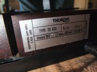
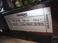
I just got a TD 320 with no wall wart. I have been unable to find a stick replacement on the internet. I was wondering if anyone knows the specs on this item. AC or DC, Voltage, amperage?
Thanks
Thanks
The wall wart (ac adaptor) looks like this from follow URL:I just got a TD 320 with no wall wart. I have been unable to find a stick replacement on the internet. I was wondering if anyone knows the specs on this item. AC or DC, Voltage, amperage?
Thanks
http://i.ebayimg.com/00/s/MTIwMFgxNjAw/z/2lEAAOSwBLlVewz1/$_3.JPG
I have measured all voltages under the different modes (wall voltage was 233VAC).
1) off-mode: 18V6AC (same value also at disconnect AC plug)
2) ON, stop-mode: 18V0AC and 22V8DC behind rectifier
3) ON, play-mode: 16V5AC and 19V2DC behind rectifier (across the main capacitor 1000uF, 35V).
Now a question: For the motor control Unit No 214753 (PCB No 6 646 056) of the second version (Thorens TD320 MKII) I am looking for the schematic. This is different from the schematic of the first version - go to
Thorens TD320 Manual - 2-Speed Belt-Drive Turntable - Vinyl Engine
http://www.theanalogdept.com/images/spp6_pics/TT manuals/Thorens/TD3xxsvcman/3xx08.jpg
http://www.theanalogdept.com/images/spp6_pics/TT manuals/Thorens/TD3xxsvcman/3xx09.jpg
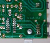
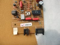
I need it to find out the reason for a burnt resistor, which is connected between the GND for motor control and the signal GND - go to
http://new-hifi-classic.de/Gallery/albums/userpics/normal_img_5401.jpg
and
http://new-hifi-classic.de/Gallery/albums/userpics/normal_img_5402.jpg
Who can upload the wanted schematic diagram ?
And what ist the actually aim of this resistor, which is not present at TD320' first version
Thank you very much.
Last edited:
Thorens TD320 Burnt Resistor
“I need it to find out the reason for a burnt resistor, which is connected between the GND for motor control and the signal GND - go to
http://new-hifi-classic.de/Gallery/albums/userpics/normal_img_5401.jpg”
I’m curious if you ever figured out anything about this burnt resistor. I have the same pcb on my Thorens TD320 with the same burnt out resistor. I’m hoping I can replace it but I can’t find any information. I picked up this TT at a garage sale very cheap and in poor shape, but I like a challenge. Any help would be appreciated.
Hi!
I have the same problem with the 320 mkii.
I found that burnt resistor, but I cant make it works again.
Did you finally get the solution? Thanks
I have the same problem with the 320 mkii.
I found that burnt resistor, but I cant make it works again.
Did you finally get the solution? Thanks
I have owned a Thorens TD-321 since I bought it new in 1984. The 321 is the version without a tonearm. I also have a TD-320 MK3 for the past 5 years. They use a 16vac wall wart. I upgraded to a GBC rated at 1.25A instead of the original 100mA version with no problems. I bought them at American Science and Surplus in Geneva, IL. They cost $4.50 each, they have 1A and 1.25A versions.
American Science and Surplus
It sounds like the resistor issue is caused by to high of voltage for the wall wart.
American Science and Surplus
It sounds like the resistor issue is caused by to high of voltage for the wall wart.
Attachments

For NOS Thorens parts, go to Ebay and look for VOLANTE1, she is in Switzerland and has the largest collection I know of. Very knowledgeable and easy to work with. Highly recommended.
I have owned a Thorens TD-321 since I bought it new in 1984. The 321 is the version without a tonearm. I also have a TD-320 MK3 for the past 5 years. They use a 16vac wall wart. I upgraded to a GBC rated at 1.25A instead of the original 100mA version with no problems. I bought them at American Science and Surplus in Geneva, IL. They cost $4.50 each, they have 1A and 1.25A versions.
American Science and Surplus
It sounds like the resistor issue is caused by to high of voltage for the wall wart.
Thanks for answering elwood, but I have the same problem than tiefbassuebertr in this post.
I have the same burnt resistor in my board and the TT doesn't work. I changed it but nothing happens.
I upgraded to a GBC rated at 1.25A instead of the original 100mA version with no problems.
...and with no improvements either, I'd guess?
Best regards!
Actually it improved the speed variations that the speed control could not handle on my TD -321 MK2. I did need to readjust the 33 and 45 rpm speeds using the two pots on the speed control board. Now both 33 and 45 rpm are dead stable.
The TD-320 MK3 uses a 24 pole motor with improved speed control, the updated wall wart was only helpful when the local mains were fluctuating. I live a mile away from Fermi Lab, when they fire up the light dim.
The TD-320 MK3 uses a 24 pole motor with improved speed control, the updated wall wart was only helpful when the local mains were fluctuating. I live a mile away from Fermi Lab, when they fire up the light dim.
TD-320 info
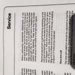
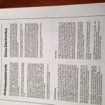
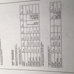
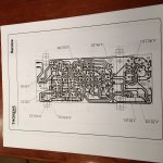
adelcura - Here is info from my TD-320 Service manual. If your turntable has the Thorens arm, it has an auto shut off feature, this is the first page, the other two pages give electrical info and test point values.
adelcura - Here is info from my TD-320 Service manual. If your turntable has the Thorens arm, it has an auto shut off feature, this is the first page, the other two pages give electrical info and test point values.
Attachments
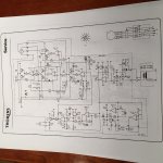
TD 320 scematics
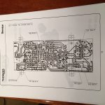
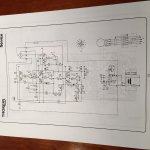
Here are the two different schematics for the speed control unit and PC boards, you will need to match the schematic to your speed control.
I hope this helps you, these are outstanding turntables which will match almost any current VPI and are certainly better than any REGA, I know, I have a P8 with the NEO speed control.
Attachments
Interesting info elwood! I have a TD320 (mkI) which I bought new back in the '80s and am going to put back into service in a bit. I always lusted after the mkII/III with the TP90 arm...
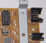
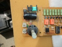
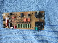
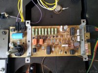
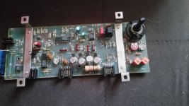
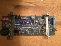
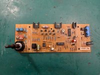
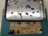
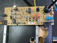
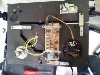
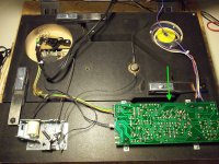
From the motor control unit of TD320 there are different versions. In the moment I want to have a service manual or service bulletin to the board from the first five attached images. Main difference to the most other find on the web are additional 8 pcs. 3W resistors of 22R, connected in the collector traces of the four complementary buffer stages.
Maybe the associated service manual is from an other model. Who know this ?
Thanks for advices.
P.S.: some URL's to Thorens TD320 for images:
https://ultragroove.tokyo/tag/thorens-td320mk2/
https://buergerrechtler-micha.blogspot.com/2020/12/thorens-motor-steuerungs-fix-td280-td.html
http://www.hifi-forum.de/viewthread-26-14675.html
Attachments
-
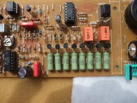 Thorens TD320 PCB 6646016 8x22R.JPG520.6 KB · Views: 61
 -
 Thorens TD320 PCB 6646016 470µF 63V S+M LL-II.JPG508.8 KB · Views: 63
 -
 Thorens TD320 PCB 6646016 quad comparator.JPG450.4 KB · Views: 57
 -
 Thorens TD320 PCB 6646016 470µF 63V S+M LL.JPG756.3 KB · Views: 64
 -
 Thorens TD320 PCB 6646016 8x22R-III.jpg63.3 KB · Views: 62
 -
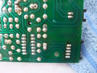 Thorens TD320 PCB 6646016 solder side.JPG565.3 KB · Views: 62
 -
 Thorens TD320 PCB-III.jpg199.4 KB · Views: 63
 -
 Thorens TD320 PCB-IV.jpg108.2 KB · Views: 63
 -
 Thorens TD320 MK-II PCB-I.jpg84.7 KB · Views: 61
 -
 Thorens TD320 MK-II PCB-II.jpg80.6 KB · Views: 64
 -
 Thorens TD320 PCB-I.webp299.4 KB · Views: 64
 -
 Thorens TD320 PCB 6646016 8x22R-II.jpg86.6 KB · Views: 61
 -
 Thorens TD320 PCB-II.jpg176.5 KB · Views: 68
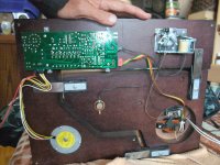
attached TD320 images of whole device from first five images in post #16
schematics under
https://archives.doctsf.com/documents/afficher_document.php?num_doc=106001&num_fic=1
are both different to this PCB
Now I have check a 14V~/270mA version from power supply series FW6299 (wall wart AC/AC adaptor ), TIPTEL order code 4569120, made for Tiptel 270 cord phone:
DC-values at TP1 (C101) : 0V7 without load and 17,9VDC with running turntable motor on 33rpm and 45rpm
AC-values at 233VAC mains voltage: 14,8V~ without load and 14,3V~ with running turntable motor on 33rpm and 45rpm.
The record player sound fine and no thermal issues are to observe on this wall wart AC/AC adaptor.
Images of this power supply from TIPTEL in post #1 under
Thorens outdoor plug-in Power Supply (AC/AC Adaptor) for TD 180-280-316-318-320-321
No 12-15
Attachments
-
 Thorens TD320 PCB 6646016 sticker back panel-II.JPG583 KB · Views: 55
 -
 Thorens TD320 PCB 6646016 sticker back panel.JPG506.1 KB · Views: 56
 -
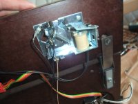 Thorens TD320 PCB 6646016 lift mech.JPG520.3 KB · Views: 54
 -
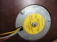 Thorens TD320 PCB 6646016 Motor.JPG639 KB · Views: 58
 -
 Thorens TD320 PCB 6646016 lift mech-II.JPG762 KB · Views: 60
 -
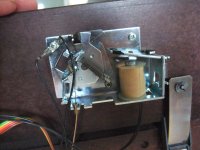
 Thorens TD320 PCB 6646016 autom switch-off.JPG810.7 KB · Views: 58
 -
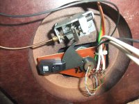
 Thorens TD320 PCB 6646016 whole bottom view.JPG781.4 KB · Views: 56
Last edited:
- Home
- Source & Line
- Analogue Source
- Thorens TD 320 Power Supply