Hi,
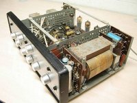
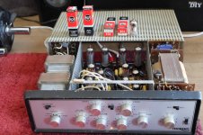
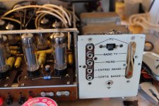
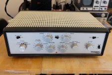
I post here the restoration of my Thorens AZ-25 tube amplifier. It was not in good conditions when I got it. It's a amp I bought two years ago and now I have decide to restore it.
All the tubes are dead, Hunt signal caps are cut in two most of the time. Decoupling capacitor have been change by the previous possessor but they are not well soldered.
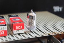
I have a new paired quad of RCA 6973 tube, 6N2P-ev tubes for pre amplification, new AVX signal capacitors, power resistors, and input / output connectors.
I will clean it and repaint it also.
If you have suggestion 😉
I post here the restoration of my Thorens AZ-25 tube amplifier. It was not in good conditions when I got it. It's a amp I bought two years ago and now I have decide to restore it.
All the tubes are dead, Hunt signal caps are cut in two most of the time. Decoupling capacitor have been change by the previous possessor but they are not well soldered.
I have a new paired quad of RCA 6973 tube, 6N2P-ev tubes for pre amplification, new AVX signal capacitors, power resistors, and input / output connectors.
I will clean it and repaint it also.
If you have suggestion 😉
Attachments
Last edited by a moderator:
You can find here the schematic. 🙂
Thorens AZ-25 and PR-24 are the same. Only the main rectification stage change.
Thorens AZ-25 and PR-24 are the same. Only the main rectification stage change.
Attachments
-
 thorens 3.jpg359.6 KB · Views: 597
 -
 thorens2.jpg991.8 KB · Views: 592
 -
 thorens1.jpg996.2 KB · Views: 728
 -
Thorens_PR24_4.pdf507.6 KB · Views: 339
-
Thorens_PR24_3.pdf425.6 KB · Views: 278
-
Thorens_PR24_2.pdf460.1 KB · Views: 292
-
Thorens_PR24_1.pdf443.6 KB · Views: 304
-
Thorens%20AZ_25.pdf217.5 KB · Views: 427
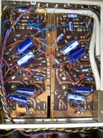
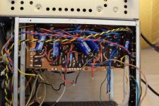
I remove the first card. There is a lot of work to do ! 
I desoldered a lot of cable. There is dust on the PCB and on the components. It is hard to remove. Signal cables are done with coaxial type. The ground is soldered on the potentiometer shield.
I test the mustard capacitors and they are OK. I only have to change one broken.
I desoldered a lot of cable. There is dust on the PCB and on the components. It is hard to remove. Signal cables are done with coaxial type. The ground is soldered on the potentiometer shield.
I test the mustard capacitors and they are OK. I only have to change one broken.
Attachments
Last edited:
I looked at the 1st of the linked schematics. It shows 12AX7/ECC83s. While the triodes in the Russian 6n2p are "equivalent", it is not a drop in replacement. You indicate the presence of printed circuit boards (PCBs). Adapting to a different pin out is difficult, under those conditions.
FWIW, I suggest you acquire Sovtek 12AX7LPS tubes.
Best wishes for success in this restoration project.
FWIW, I suggest you acquire Sovtek 12AX7LPS tubes.
Best wishes for success in this restoration project.
Hi,
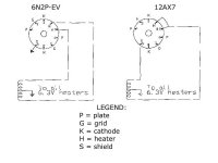
Thanks Eli for your response. I will go with the 6N2P because I like them and I have them in my stock. Yes I know it is not the same PINOUT.
I have already start to modify the board for the 6N2P. They required 6.2V for the heaters voltage (not 12V). I had to cut PIN 4 and 5. I soldered the heater power supply on 4 and 5 and GND on PIN 9 for the internal shield.
Thanks for your suggestion 😉 I will look at the Sovtek 12AX7LPS tubes. Have you compare it to other tubes ?
Attachments
Last edited:
Hi,
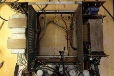
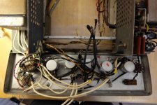
I am working on the project. I have remove the two pcbs and the front panel to have more access on the amplifier.
Signal capacitor have to be change on the front panel too.
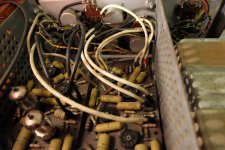
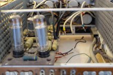
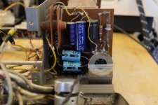
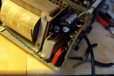
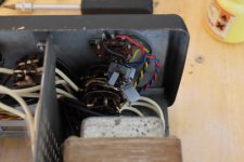
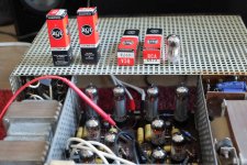
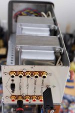
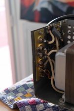
I took pictures of the input main power supply and the rectification stage.
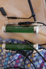
Do you know what is the role of the little transformer (on picture 11) and the two plate system (on picture 10) ? Thanks 🙂
I am working on the project. I have remove the two pcbs and the front panel to have more access on the amplifier.
Signal capacitor have to be change on the front panel too.
I took pictures of the input main power supply and the rectification stage.
Do you know what is the role of the little transformer (on picture 11) and the two plate system (on picture 10) ? Thanks 🙂
Attachments
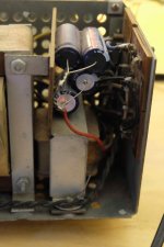
Do you know what is the role of the little transformer (on picture 11) and the two plate system (on picture 10) ? Thanks 🙂
Hi,
What you call the "two plate system" looks like a selenium rectifier (google it). The number of stacks of plates is proportional to the PIV (peak inverse voltage). Hope that it helps.
Regards,
Maxime
Hi,
Yes thanks it look like a selenium rectifier, I think it is "tm-2002" on schematic. I don't know why there is two type of diode. It should be because selenium diode was rated with more power.
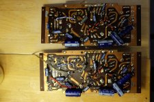
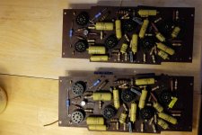
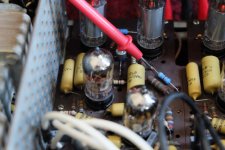
Here the pictures of the board restauration. I changes the potentiometer, some resistors (perhaps I should change the other big one, but the value is ok). I also change one mustard capacitor and the signal capacitors. The decoupling capacitor have been re soldered and I try to optimise the placement.
The boards are clean, it is much better !
I change the preamp tube PINOUT. Hope it will be ok 😉
Yes thanks it look like a selenium rectifier, I think it is "tm-2002" on schematic. I don't know why there is two type of diode. It should be because selenium diode was rated with more power.
Here the pictures of the board restauration. I changes the potentiometer, some resistors (perhaps I should change the other big one, but the value is ok). I also change one mustard capacitor and the signal capacitors. The decoupling capacitor have been re soldered and I try to optimise the placement.
The boards are clean, it is much better !
I change the preamp tube PINOUT. Hope it will be ok 😉
Attachments
Last edited:
A would not call this work "revox restauration" it more of a scratch build with a revox chassies.
Restauration in my world refers to bringing back to original shape & form.
BTW, did the amp work before ?
Restauration in my world refers to bringing back to original shape & form.
BTW, did the amp work before ?
Hi,
Petertub, I mean restauration because I replace the fail part with new parts with the same values. The only change is the preamp tube PINOUT to fit the 6N2P-ev and it can be reverse easily.
Do you mean it is not a good work that I am doing ? Not the good way ? Thanks
The amp was not working properly, signal caps were cut is two, tubes was weaks. There were sound only on one channel.
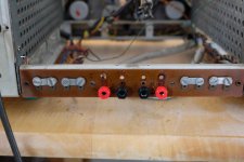
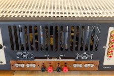
Here some more picture. I add some banana plug on the output, replace others signal capacitor, add a good power supply cable with earth protection to chassis. And I replace one weak capacitor on main power supply.
The two board are back in place for test and bias settings 🙂
You are all welcome to comment and don't hesitate if you have advices on the restauration. Thanks 🙂
Petertub, I mean restauration because I replace the fail part with new parts with the same values. The only change is the preamp tube PINOUT to fit the 6N2P-ev and it can be reverse easily.
Do you mean it is not a good work that I am doing ? Not the good way ? Thanks
The amp was not working properly, signal caps were cut is two, tubes was weaks. There were sound only on one channel.
Here some more picture. I add some banana plug on the output, replace others signal capacitor, add a good power supply cable with earth protection to chassis. And I replace one weak capacitor on main power supply.
The two board are back in place for test and bias settings 🙂
You are all welcome to comment and don't hesitate if you have advices on the restauration. Thanks 🙂
Attachments

Last edited:
Restoration means to me, restoration to original form and function.
Replacing ecc83 to something else is modification ( and maybe not
an improvement at all). Same with cutting circuit boards, this is non-reversable and
voids the restoration.
So what you present is a scratch build that looks like a revox. Maybe an improvement
or maybe not. But it is not a revox anymore.
Ok, I really like the sound of 6N2P-EV and when I see now the price of NOS 12AX7 tubes... If I have the occasion to buy some good NOS 12AX7 tube I'll do adaptors to listened to them and compare. 😉
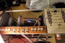
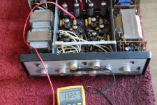
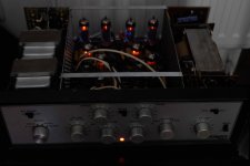
I power up the amp with all the new tubes. No problems all seems to be OK. I have the 6.3 voltage on the heaters. I bias the power tubes.
I run some tracks and the sound is very good ! 😀
I compare it rapidly to my Aleph J and it is great. Not the same sound but great too. Very good on voices and jazz.
Next step is to change the input jack connectors, run a scope test with a GBF and do more cleaning and painting.
Attachments
Hi,
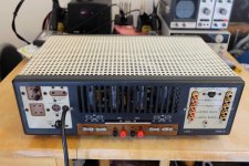
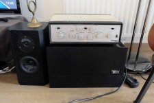
Here some advance on the project. I spend a lot of time to clean the rust and painting... it is not perfect but the amp look mutch better !
I made custom pcb with CNC to replace the input connectors, they were very difficult to remove.
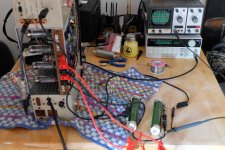
I am doing first measurement on the amp, all seems to be ok. Channel are paired on 100Hz - 20KHz. Gain is not flat but I think it is normal on this type of amplifier.
I use 5.6 ohm Vishay power resistor to replace HP on the bench. Very useful 😉
Here some advance on the project. I spend a lot of time to clean the rust and painting... it is not perfect but the amp look mutch better !
I made custom pcb with CNC to replace the input connectors, they were very difficult to remove.
I am doing first measurement on the amp, all seems to be ok. Channel are paired on 100Hz - 20KHz. Gain is not flat but I think it is normal on this type of amplifier.
I use 5.6 ohm Vishay power resistor to replace HP on the bench. Very useful 😉
Attachments
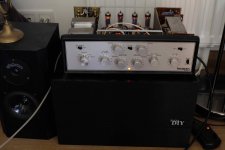
It found is place on the Aleph J.
I was planning to restaure it and sell it but my gf prefer the sound of the Thorens over my other amplifier... So it will stay here a little time 😉
I was planning to restaure it and sell it but my gf prefer the sound of the Thorens over my other amplifier... So it will stay here a little time 😉
Attachments
Hello Matt (?),
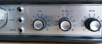
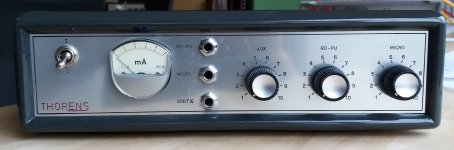
I found your thread, looking for info on my Thorens preamps. They look like the same family as your power amp.
I would like to know more about them; they are mono and I have two.
Do you have any info or schematics for these units?
Jan
I found your thread, looking for info on my Thorens preamps. They look like the same family as your power amp.
I would like to know more about them; they are mono and I have two.
Do you have any info or schematics for these units?
Jan
Attachments
Hello Jan,
Have you found the schematic for your Thorens preamps ?
Do you like them, can you send us picture of the inside ? 🙂
Have you found the schematic for your Thorens preamps ?
Do you like them, can you send us picture of the inside ? 🙂
No I haven't found the schematic. But it seems that the section I thought was a RIAA preamp is actually the bias generator for a tape recorder!
So this is a preamp with few inputs including tape recording, and with the bias generator included.
Jan
So this is a preamp with few inputs including tape recording, and with the bias generator included.
Jan
It found is place on the Aleph J.
I was planning to restaure it and sell it but my gf prefer the sound of the Thorens over my other amplifier... So it will stay here a little time 😉
Nice job! How does it sounds?
- Status
- Not open for further replies.
- Home
- Amplifiers
- Tubes / Valves
- Thorens AZ-25 restoration