SlouGan said:
Sorry gangs if this is a bit off topic,
The problem for this PSU is, it comes off from an old server and the power switch is controlled by motherboard. Which means I have to find from the maze of power cords which pair is the turn-on cords....When I plug it in, I could not get any measure out so I think there must be some wires that need to be shorted first., do you have any suggestion?
On the mo'board connector pin 14 (ATX formfactor)is the ground for the connection for the psu to MB. Ground it out to the case of the power supply and the supply should power up. The wire is usually green. This is in addition to any other connections you need. It might work with just that one pin grounded out.
Bricolo,
You are not being very methodical about solving your problems. There is a giant list of posts from you in which you either ignore advice or halfheartedly implement it. A lot of people have tried to help you out, but if you continue to jump from idea to idea I don't think you will ever solve your problems.
Since your oscillation could be fixed by any number or combination of the suggestions given you must methodically implement them until you get it working, then try to strip out things like extra ground points, zobels, output resistors, etc. I feel that you are asking questions, getting good advice, ignoring it, and moving on to a new question without addressing the first one.
This is a waste of time for you and others, because if the 2nd of 5 suggestions would have solved your problem then more esoteric atempts are not going to work. Troubleshooting means carefully addressing each potential problem IN ORDER.
tell me if I'm wrong, but I tested every advice I've been given
-rewireing everything properly-> done it with cat5e wire
-adding a 200uF to supply rails-> done
-trying a 10R+0.1uF zobel-> also done
-puting an input cap-> added a 4.7uF wima one
I'll buy 9.5K resistors to put on +In, to give a try
and I'm also working on a case
what haven't I tryed?
-rewireing everything properly-> done it with cat5e wire
-adding a 200uF to supply rails-> done
-trying a 10R+0.1uF zobel-> also done
-puting an input cap-> added a 4.7uF wima one
I'll buy 9.5K resistors to put on +In, to give a try
and I'm also working on a case
what haven't I tryed?
"what haven't I tryed?"
Shorten all wires.
IMHO I think there is half-a-metre too much wire?
Arne K
Shorten all wires.
IMHO I think there is half-a-metre too much wire?
Arne K
Bricolo said:tell me if I'm wrong, but I tested every advice I've been given
-rewireing everything properly-> done it with cat5e wire
-adding a 200uF to supply rails-> done
-trying a 10R+0.1uF zobel-> also done
-puting an input cap-> added a 4.7uF wima one
I'll buy 9.5K resistors to put on +In, to give a try
and I'm also working on a case
what haven't I tryed?
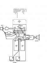
if your star ground is on your bridge rectifiers as i think it is, try moving the star ground nearer the chip (see image).
Peter Daniels is trying you to get you to connect the grounds of the speakers together directly at the amp-side connectors as well as to star ground (see second post).
did you say that you throught that you had damaged one of the chips and that you thought that that was causing the oscilations? if so, have you tried using new chips?
Attachments
Also, if you are using minimized GC schematic without grounded chassiss, the hum and oscillations might be caused by that.
what haven't I tryed?
One word........... Ampkit.
ampkit@triad.rr.com
http://www.scott-nixon.com/dac.htm
Yes, when an amp oscillates it is often at a frequency greater than its closed loop bandwidth.
One word........... Ampkit.
ampkit@triad.rr.com
http://www.scott-nixon.com/dac.htm
Yes, when an amp oscillates it is often at a frequency greater than its closed loop bandwidth.
Attachments
gainclone for ribbons?
To drive ribbons (Ravens/ESg/ CG) or say Seas Millennium tweeters:
How would the gainclone go?
http://www.diyaudio.com/forums/showthread.php?s=&postid=147914#post147914
To drive ribbons (Ravens/ESg/ CG) or say Seas Millennium tweeters:
How would the gainclone go?
http://www.diyaudio.com/forums/showthread.php?s=&postid=147914#post147914
Mad_K said:
This is because the OPA547/8/9 is set to the max I_lim if you put V- on it (internal R) This feature insn't present in the OPA541, so in order to have I_lim (and short-circuit protection), you MUST use a resistor. The size if this R i determined by the SOA chart. Please read the datasheets...
😉 You could ommit the R ofcourse (as I did in my test-setup), but then you're not protected...
what resistor should i use to get the maximum currnet limit? i used the formula in the datasheet and got 0.1ohm, but this is tiny, is this correct? if it is, i can get 3, 5 and 7watt versions.
Matttcattt said:
if your star ground is on your bridge rectifiers as i think it is, try moving the star ground nearer the chip (see image).
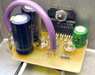
Hi,
your bridges wireing is wrong (not both - together)😉
My experimental bloks with TDA7293 is on picture.
(without mute-stby components)
Regards
Attachments
the zobel saga..
Hi bricolo!!
The ground side of the zobel must conect to the power suplly ground!!The midle point of the power suplly capacitors...not the signal ground!
Not at the speakers binding posts..please!!
Hi bricolo!!
The ground side of the zobel must conect to the power suplly ground!!The midle point of the power suplly capacitors...not the signal ground!
Not at the speakers binding posts..please!!
power supply
Nuuk,
Thanks for the reply. CPU was an example. I agree. I think that a fixed connection would be the optimal setup. I'll probably go that way.
vic
Nuuk,
Thanks for the reply. CPU was an example. I agree. I think that a fixed connection would be the optimal setup. I'll probably go that way.
vic
Matttcattt said:
if your star ground is on your bridge rectifiers as i think it is, try moving the star ground nearer the chip (see image).
Peter Daniels is trying you to get you to connect the grounds of the speakers together directly at the amp-side connectors as well as to star ground (see second post).
did you say that you throught that you had damaged one of the chips and that you thought that that was causing the oscilations? if so, have you tried using new chips?
I use 2 bridges in my stereo amp
so both chips are connected to the same star ground
and so, the speaker's - are also connected to the sema stargound
The_Dude: my analog ground is connected to earth, directly
Sorry again, but I promise this is the last post regarding this stupid computer PSU.Philo said:
On the mo'board connector pin 14 (ATX formfactor)is the ground for the connection for the psu to MB. Ground it out to the case of the power supply and the supply should power up. The wire is usually green. This is in addition to any other connections you need. It might work with just that one pin grounded out.

Here is the pic of the power supply connectors to mo'bo, the blue is also appear in all other connectors, but yellow and white and orange only appear in the connectors to mo'bo.
Which one should I try to ground it to get the PSU switch on?
Thanks
you have 2 wires: ps on and ps good (a grey one and a green one)
connect those 2 together, and the psu switches on 🙂
connect those 2 together, and the psu switches on 🙂
SlouGan,
Hmm, An old one indeed. Time for you to do a little troubleshooting and open the case. Crack the case and look at the source of the wires. Most should come from some kind of terminals for supply and return of the power. There will probably be about 4-5 wires left over or go to a different terminal. Look for the ones that come from an area around the power regulation area and are kind of off by themselves. Your right in thinking there might be two wires involved, but you might still need a load as suggested before. Try groung ing the different ones. Do you have a load resistor to put on a couple of the wires. The red and yellow are usually +12 and +5. I am going by the insides of two old atx server psu's I am looking at so don't quote me but this is how I learned it originally. Email me with anymore questions if you don't want to post them. I just remembered that you can look in a Pocket Ref for PCs, its usually blue not black like the regular one. They have them at most electronic stores for <$12. It should have the pinout of the power supply.
Hmm, An old one indeed. Time for you to do a little troubleshooting and open the case. Crack the case and look at the source of the wires. Most should come from some kind of terminals for supply and return of the power. There will probably be about 4-5 wires left over or go to a different terminal. Look for the ones that come from an area around the power regulation area and are kind of off by themselves. Your right in thinking there might be two wires involved, but you might still need a load as suggested before. Try groung ing the different ones. Do you have a load resistor to put on a couple of the wires. The red and yellow are usually +12 and +5. I am going by the insides of two old atx server psu's I am looking at so don't quote me but this is how I learned it originally. Email me with anymore questions if you don't want to post them. I just remembered that you can look in a Pocket Ref for PCs, its usually blue not black like the regular one. They have them at most electronic stores for <$12. It should have the pinout of the power supply.
Matttcattt said:
what resistor should i use to get the maximum currnet limit? i used the formula in the datasheet and got 0.1ohm, but this is tiny, is this correct? if it is, i can get 3, 5 and 7watt versions.
5 Watt is enough.
I would use 0,15 ohm for OPA541AP, and 0,1 ohm for OPA541AM.
- Status
- Not open for further replies.
- Home
- Amplifiers
- Chip Amps
- This is not just another gainclone