My advice to Bricolo...(reprise)
Many moons ago i advice you tu put a Zobel at the output!!
Many folks after me tell you the same thing!!!...The devil as nothing to do with oscilations...bad design yes!!
The reason!
In a 8 Ohm load you got no oscilation!...
In a loudspeaker load you got oscilation because the load in this case is inductive...with the zobel the amplifier will "see" a resistive load in the highs frequencys...and will behave as in the resistive load!
Peter Daniel said:
Try to connect both channels output grounds with a piece of wire. It worked in my friend's setup.
what do you mean?
theyr have no output gound
I pick up speaker's ground from analog ground
All my gainclones had no problems so far, yet in one setup, for some reason the amp was picking up some freguencies and was possibly oscillating as well. I had the chassis gound connected to one channel analog ground only. I advised the guy to connect L and R channel speaker posts (connected to ground) together with a jumper and the problem disappeared.
Bricolo,
Your problems are almost certainly due to layout. Even just a short length of wire can act as inductor, which will provoke oscillations in any high-gain op-amp circuit. My GainClone has no Zobel network at the moment, and is perfectly fine.
However, I will add them to the final versions, as they will help to ensure stability into awkward loads. It shouldn't harm the sound quality, and you shouldn't be afraid to use them. But it is wise to ensure that your amp is stable without them...
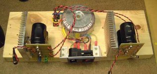
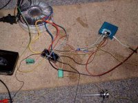
Mine take about 25-30mA per IC at idle, and run cold. Take a close look at the pictures on this thread (and on my GainClone page) for examples of good layout practice. It really does matter!
Post us a picture of your current setup, and we'll try to help 😉 If the above picture is yours, then definately rebuild it!
Fedde,
I didn't mention the sound as the post seemed a bit long, and I'd put some comments on my homepage. But, first impressions are really encouraging - really clean, detailed, dynamic. Even with just one 120VA transformer...
Your problems are almost certainly due to layout. Even just a short length of wire can act as inductor, which will provoke oscillations in any high-gain op-amp circuit. My GainClone has no Zobel network at the moment, and is perfectly fine.
However, I will add them to the final versions, as they will help to ensure stability into awkward loads. It shouldn't harm the sound quality, and you shouldn't be afraid to use them. But it is wise to ensure that your amp is stable without them...
Mine take about 25-30mA per IC at idle, and run cold. Take a close look at the pictures on this thread (and on my GainClone page) for examples of good layout practice. It really does matter!
Post us a picture of your current setup, and we'll try to help 😉 If the above picture is yours, then definately rebuild it!
Fedde,
I didn't mention the sound as the post seemed a bit long, and I'd put some comments on my homepage. But, first impressions are really encouraging - really clean, detailed, dynamic. Even with just one 120VA transformer...
plug your scope to the speaker, and watch 🙂cowanrg said:how exactly can you tell if your amp is oscillating?
Hi Bricolo!
Like I postetd before, try shortening the wires (a lot). The GainClone layouts suggested by P. Daniels and others really rely on short signal paths to the IC, especially with the supply caps. Also the TDA is a little bit more picky about surroundings...
Look at
http://www.ub-elektronik.de/download/a100-daten-301.pdf
On page 5 of this document you can see the layout of this (in Germany) popular DIYamp using TDA. He uses a Zobel...
The original ST layout uses a Zobel...
Simply try it once. If it doesn't help, you know at least that this solution did not work.
I would say layout refinements could help to some extend, but maybe you really need a zobel.
I have rebuild my GC for six times now (both channels), it doesn't really take that long!
Bye,
Arndt
how can i break in the gainclone i am going to build without listnig to music? will putting a 8ohm resistor across the output work?
Place two speakers face to face and wire them in reverse polarity.
Feed mono signal to both amplifier channels and crank them at medium level.
After a delay, run them up to clip briefly and the sound will change and stabilise.
Eric.
Feed mono signal to both amplifier channels and crank them at medium level.
After a delay, run them up to clip briefly and the sound will change and stabilise.
Eric.
would this circuit work? and either way, would i be correct in thinking that 100v at 12A would be 1200watts???!!!??? 
An externally hosted image should be here but it was not working when we last tested it.
Peter Daniel said:All my gainclones had no problems so far, yet in one setup, for some reason the amp was picking up some freguencies and was possibly oscillating as well. I had the chassis gound connected to one channel analog ground only. I advised the guy to connect L and R channel speaker posts (connected to ground) together with a jumper and the problem disappeared.
my stereo amp uses one ground for both channels, so I haven't this problem
they use the same 2 diode bridges as well, and I saw that disconnecting one speaker, stops oscillations at the other
do you think that using 2 bridges per channel would help?
Bricolo said:
my stereo amp uses one ground for both channels, so I haven't this problem
Where is the common point?
Bricolo said:
my stereo amp uses one ground for both channels, so I haven't this problem
they use the same 2 diode bridges as well, and I saw that disconnecting one speaker, stops oscillations at the other
do you think that using 2 bridges per channel would help?
My GC (connected both sides to same bridge) had the same probs. What do you have connected the non-inverting input to? I had it connected directly to ground (like in the simplified schematic), and as soon as I connected the second channel: Oscillations... and distortions...
That changed after I put a biasing resistor (of about 9.5 kohms, if you use 10k to inverting input, and 220 k as feedback), bypassed with 0.1 uF MKP from the non-inverting input to ground.
And don't ignore all other input you received so far. It seems that you don't want to do any changes to your setup whatsoever...

Bye,
Arndt
BTW: Peter, will those diode you use for GC (MUR820) also suffice for the P3A I am building
 (I mean the 8A)? I target 2*80 - 2*110 W into 8 ohms, with a single bridge build out of the diodes. Supply voltage is 42 V (30 - 0 - 30 500 VA toroid)??
Peter Daniel said:
Where is the common point?
do you see my 2 diode bridges on the picture posted before?
they are connected on the ground point with 2 big section solid wires
all grounds are directly soldered on this cable connecting the 2 diode bridges
I don't know if one bridge is OK. If you want to use those diodes I would go at least with 2 bridges. And the diodes are MUR860 not 820 and either Motorola or On Semi parts.😉
you had the same problem, do you mean HF oscillation at the speakersCradle22 said:
My GC (connected both sides to same bridge) had the same probs. What do you have connected the non-inverting input to? I had it connected directly to ground (like in the simplified schematic), and as soon as I connected the second channel: Oscillations... and distortions...
That changed after I put a biasing resistor (of about 9.5 kohms, if you use 10k to inverting input, and 220 k as feedback), bypassed with 0.1 uF MKP from the non-inverting input to ground.
And don't ignore all other input you received so far. It seems that you don't want to do any changes to your setup whatsoever...
Bye,
Arndt
BTW: Peter, will those diode you use for GC (MUR820) also suffice for the P3A I am building
no oscillation when using a dummi resistance load
and no oscillation with only one speaker connected (the other channel's output being disconnected)
?
I'll try the +in resistor trick
that's not I want to ignore the advices I've been given, I'm only affraid of having something in parallel to the speaker, that could decrease the sound
thanks to all for your advices 🙂
I just tested one more PS filtering cap directly on the chip
I put a 220uF on the +, and another on the -
stupid as I am, I bought 2, and I realised I needed 4, with a stereo amp...
so for now, only one side has those 2 220uF caps.
the other channel oscillates even more now! with the other channel's ( the one with the 2 new caps) speaker disconnected it still oscillates
but the speaker attached to the chip that has those 2 caps no more oscillates 🙂
even at high volume, even when the other channel's speaker is connected 🙂
great, I'll buy the 2 other ones 🙂
the bad point is that this side has now more hum :/ quite strange, since I added filtering caps
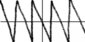
I looked the +V and -V signals at the scope, and my part of AC hasn't decreased, strange
it's still 300mV peak to peak, with a curve like the one in attached file
frequency is 100Hz (this only thing is normal)
PS: of course, I used the scope on AC, I don't only have 300mV AC, I also have 24.5V DC 😀
I put a 220uF on the +, and another on the -
stupid as I am, I bought 2, and I realised I needed 4, with a stereo amp...
so for now, only one side has those 2 220uF caps.
the other channel oscillates even more now! with the other channel's ( the one with the 2 new caps) speaker disconnected it still oscillates
but the speaker attached to the chip that has those 2 caps no more oscillates 🙂
even at high volume, even when the other channel's speaker is connected 🙂
great, I'll buy the 2 other ones 🙂
the bad point is that this side has now more hum :/ quite strange, since I added filtering caps
I looked the +V and -V signals at the scope, and my part of AC hasn't decreased, strange
it's still 300mV peak to peak, with a curve like the one in attached file
frequency is 100Hz (this only thing is normal)
PS: of course, I used the scope on AC, I don't only have 300mV AC, I also have 24.5V DC 😀
Attachments
- Status
- Not open for further replies.
- Home
- Amplifiers
- Chip Amps
- This is not just another gainclone