yes, most AD's are smt, that sucks :/Hamish said:yeah, i used a preamp with the chip using the opa2134. it was a rod elliot one. sounds nice (but i don't know if i'm all that fussy with stuff i build myself. pride, maybe?). i definitely prefer it with than without. if i can get up the nerve to do it, i'll try some ad8021 chips that came last week. i wish i had checked if they were surface mount. oh well.
Hi,
Not wanting to diss Nelsons Designs here, but the superior sound via the "balanced" input (really pseudo balanced) was not a function of the "balanced" input as such, but of the way the BOSOZ Preamp works. It is not a good idea at all to use this preamp or any other similar differential topology (like with Valves) via an unbalanced output.
I suspect a Single-Ended BOZ Preamp would ultimatly be a better match, or even better a decent 5687 based single ended valve linestage....
Sayonara
I should also say that both amps were being run balanced from a Bosoz preamp. The balanced input on the gc (as in the Aleph) sounds more dynamic and has a deeper and wider soundstage.
Not wanting to diss Nelsons Designs here, but the superior sound via the "balanced" input (really pseudo balanced) was not a function of the "balanced" input as such, but of the way the BOSOZ Preamp works. It is not a good idea at all to use this preamp or any other similar differential topology (like with Valves) via an unbalanced output.
I suspect a Single-Ended BOZ Preamp would ultimatly be a better match, or even better a decent 5687 based single ended valve linestage....
Sayonara
although some ad797's turned up a few weeks ago i'm looking forward to giving a go. maybe in a phono pre. i have to say, i'm new to all this chip stuff, but i can't believe the quality that you can get for a reasonably small investment as far as time/price/space/components/experience are concerned. i think i've found my niche.....
😀
😀
where can you place the volume pot?protos said:Here you go. By the way DC offset went way down with this set up around 15mV on one and 5mV on the other.
I've checked the ICs we can use for a gainclone:
LM3875/3876
LM3885/3886
LM1875
TDA1294
TDA7294
OPA512
OPA541
OPA548
OPA549
TDA2050
TDA2040
TDA2030
TDA2020
from what I've read:
from best to worst:
TDA7294>LM3875>LM3885>TDA1514
but LM3885 has greater bass thab 3875 (would do a nice sub amp)
The LM1875 is told to sound better than a LM3875, but it's only 20W
The TDA2050 and 2040 are also tols to be very good (the 2030 and 2020 not)
OPA549 also seems good
The price of TDA2050 (and evenmore so TDA2040) is so lowHamish said:are the tda's available as samples? i'm really fond of that frugalphile(tm) quality/$ ratio.
you can call it samples.
Check it out. Should be available in most parts of the world.
At least TDA2040.
/halo - who needs samples, when it is almost free?
- you still need to buy TRAFO
Bricolo,
I understand that if you use a volume pot you might omit the 47k resistors to ground. Of course for a balanced gc you will need either two stereo vol pots or a four deck vol pot.
I understand that if you use a volume pot you might omit the 47k resistors to ground. Of course for a balanced gc you will need either two stereo vol pots or a four deck vol pot.
i know you still have to buy the transformer (and other associated parts), but it still feels so good to have the stuff turn up on your doorstep for free. psychologically it feels like the whole thing cost nothing then, and i somehow can justify buying more expensive components. donations from all chip manufacturers graciously accepted😀
where can we order transformers samples? 😀Hamish said:i know you still have to buy the transformer (and other associated parts), but it still feels so good to have the stuff turn up on your doorstep for free. psychologically it feels like the whole thing cost nothing then, and i somehow can justify buying more expensive components. donations from all chip manufacturers graciously accepted😀
Hi,
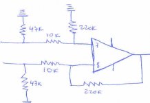
That will kind of work, but because your schematic actually does NOT balance the input impedances of the Amplifier the input will suffer very poor common mode rejection and will unbalance the volume control. The same will happen if the sourceimpedance driving the input is appreciably non-zero.
If a suficiently functional pseudo balanced input is required the following should be done:
1) disconnect the 47k resistor on the inverting input ahead of the 10k resistor
2) place a 22k resistor directly on the Chip's inverting input to ground.
3) replace the 47k resistor on positive input ahead of the 10k resistor with as close as possible to 10455 Ohm, you could use a series connection of 10k and 470 Ohm to get "close enough"
This will now make sure that both the cold (inverting) and hot (non-inverting) input impedance to ground are very close to exactly 10k and thus balanced. The gain on both inputs should be balanced too, so all on the green there.
I would again note that I do not think such an approach to be usefull in most cases and using the chipamp inverting with a 10k:10K line input transformer from a reputable manufacturer will give a much superior balanced input, but I have made that point before.
Anyway in case the pseudo balanced input is sufficiently balanced gain- and impedancewise, using an attenuator with 4 Tracks (which would have to offer a very accurate balance making a precision stepped attenuator in essence mandatory) will result in no degradation of CMRR. A larger CMRR degradation would be the case with your schematic if attenuators are used.
Of course, there is absolutely NO need to have a 4-Track volume control to make a balanced attenuator, but that as they is another story....
Sayonara
Bricolo,
I understand that if you use a volume pot you might omit the 47k resistors to ground. Of course for a balanced gc you will need either two stereo vol pots or a four deck vol pot.
That will kind of work, but because your schematic actually does NOT balance the input impedances of the Amplifier the input will suffer very poor common mode rejection and will unbalance the volume control. The same will happen if the sourceimpedance driving the input is appreciably non-zero.
If a suficiently functional pseudo balanced input is required the following should be done:
1) disconnect the 47k resistor on the inverting input ahead of the 10k resistor
2) place a 22k resistor directly on the Chip's inverting input to ground.
3) replace the 47k resistor on positive input ahead of the 10k resistor with as close as possible to 10455 Ohm, you could use a series connection of 10k and 470 Ohm to get "close enough"
This will now make sure that both the cold (inverting) and hot (non-inverting) input impedance to ground are very close to exactly 10k and thus balanced. The gain on both inputs should be balanced too, so all on the green there.
I would again note that I do not think such an approach to be usefull in most cases and using the chipamp inverting with a 10k:10K line input transformer from a reputable manufacturer will give a much superior balanced input, but I have made that point before.
Anyway in case the pseudo balanced input is sufficiently balanced gain- and impedancewise, using an attenuator with 4 Tracks (which would have to offer a very accurate balance making a precision stepped attenuator in essence mandatory) will result in no degradation of CMRR. A larger CMRR degradation would be the case with your schematic if attenuators are used.
Of course, there is absolutely NO need to have a 4-Track volume control to make a balanced attenuator, but that as they is another story....
Sayonara
KYW,
I know I didn't follow your previous recommendations which you so kindly summarised but I was following the idea behind the schematics on the Marchand Electronics amplifier module seen in a previous thread which seem have same value resistors on both inputs. Does this mean their module is not optimised?
I am sorry for being a little ignorant of EE but may I impose on you to explain how you calculate these values to get the same impedance on both inputs?
Hi,
One would HAVE to assume so... ;-)
Right, first the main reason. If the output impedance of the balanced source is not exactly zero and the balanced source is not fully floating (Transformer) then the different input impedances of the commonly used pseudo balanced inputs will cause an imbalance in signal. This IMHO tends to make the results often worse than a good unbalanced connection.
The input impedance of the "inverting chip-amp" is equal to the value of the input resistor with pretty good precision. This means the "stabilisation resistor" (inverting input to ground - 22k) and feedback resistor (220k) do not form part of the of the input impedance seen by the source.
Note however that they DO form part of the source impedance seen by the Chip Amp.
On the non-inverting input however we have an input terminat that in theory is infinite in impedance, so the input impedance seen by the source on the non-inverting amplkifier input is the series connection of the resistor to ground (220k) and the input series resistor (10k).
This means the inverting input (cold) has 10k input impedance and the non-inverting (hot) input has 230k input impedance. If we have a output impedance for the source of 300 Ohm per phase then one input will be attenuated by 0.011db and the other by 0.25db. So overall a 0.24db imbalance for the signal would be introduced by even a very modest source output impedance.
I'm not quite up to speed right now to know by how much the CMRR would be degraded (if anyone is handy with this stuff please post), but it would not be small.
So our main task is now to make that 230kOhm input impedance on the "hot" input equal to 10k. If we parallel 10475 Ohm (a 10k resistor in series with a 475R) with the "hot" input to ground (XLR Pin1) we get
230k//10k475 =
(230 *10.475)/(230+10.475) =
2409.25/240.475 = 10.018712 Ohm
So now our "cold" input shows an impedance to ground (XLR pin 1 - ground) of 10k nominal (say +/-0.5% if we use a 0.5% tolerance resistor) and our "hot" input shows an impedance to ground of 10k +0.18%, or well within the tolerance of the inverting input resistor.
If one where to make sure of maximising the CMRR absolutely then all resistors used (220k X 2, 10k X 2) should be of 0.05% tolerance. In this case the impedance matching resistor should be 10455 Ohm as accuratley as possible +/-5 Ohm look fine for 0.05%....
I hope this clarifies the issue.
Sayonara
I know I didn't follow your previous recommendations which you so kindly summarised but I was following the idea behind the schematics on the Marchand Electronics amplifier module seen in a previous thread which seem have same value resistors on both inputs. Does this mean their module is not optimised?
One would HAVE to assume so... ;-)
I am sorry for being a little ignorant of EE but may I impose on you to explain how you calculate these values to get the same impedance on both inputs?
Right, first the main reason. If the output impedance of the balanced source is not exactly zero and the balanced source is not fully floating (Transformer) then the different input impedances of the commonly used pseudo balanced inputs will cause an imbalance in signal. This IMHO tends to make the results often worse than a good unbalanced connection.
The input impedance of the "inverting chip-amp" is equal to the value of the input resistor with pretty good precision. This means the "stabilisation resistor" (inverting input to ground - 22k) and feedback resistor (220k) do not form part of the of the input impedance seen by the source.
Note however that they DO form part of the source impedance seen by the Chip Amp.
On the non-inverting input however we have an input terminat that in theory is infinite in impedance, so the input impedance seen by the source on the non-inverting amplkifier input is the series connection of the resistor to ground (220k) and the input series resistor (10k).
This means the inverting input (cold) has 10k input impedance and the non-inverting (hot) input has 230k input impedance. If we have a output impedance for the source of 300 Ohm per phase then one input will be attenuated by 0.011db and the other by 0.25db. So overall a 0.24db imbalance for the signal would be introduced by even a very modest source output impedance.
I'm not quite up to speed right now to know by how much the CMRR would be degraded (if anyone is handy with this stuff please post), but it would not be small.
So our main task is now to make that 230kOhm input impedance on the "hot" input equal to 10k. If we parallel 10475 Ohm (a 10k resistor in series with a 475R) with the "hot" input to ground (XLR Pin1) we get
230k//10k475 =
(230 *10.475)/(230+10.475) =
2409.25/240.475 = 10.018712 Ohm
So now our "cold" input shows an impedance to ground (XLR pin 1 - ground) of 10k nominal (say +/-0.5% if we use a 0.5% tolerance resistor) and our "hot" input shows an impedance to ground of 10k +0.18%, or well within the tolerance of the inverting input resistor.
If one where to make sure of maximising the CMRR absolutely then all resistors used (220k X 2, 10k X 2) should be of 0.05% tolerance. In this case the impedance matching resistor should be 10455 Ohm as accuratley as possible +/-5 Ohm look fine for 0.05%....
I hope this clarifies the issue.
Sayonara
Use of more than 2W Class-A-Mod-R?
Hi!
I just tried the so-called Class-A-Mod with a 2 (or maybe even 3) W 1.5k R between output and negative voltage, and it sounds very well, but the resistor runs very, very, very hot... you simply cannot touch it without getting burns...
So, should I maybe use a higher W rating, like 5W?
Btw., I run my LM3876 (yes, not 3875) with +- 40 V (30-0-30 toroid), which never gives me a problem so far (since the IC has a voltage rating between 18 V and about 80 V), but maybe this is too much for the resistor (so far it hasn't burned...)
Any suggestions?
Thanks,
Arndt
so-called Class-A-Mod
How many of you people actually realize that this 'mod' reduces Iq rather than increase. It would be more appropiate to call it the 'Class AB to B mod'.
gr,
Thijs
Kuei Yang Wang,
Why are you so in favor of line input transformers? I see some benefits (much better CMRR in most cases) but also some detriments (much worse THD, especially at very low frequencies). Is trading THD for CMRR really worth it? Probably the most useful aspect of balanced interconnects is ground loop removal/shield in the signal path, which hold true regardless of the CMRR.
This is not an attack--I am honestly interested in your thoughts.
balance....or bridge...?
how about using on of these... :
texas instru. drv134
http://focus.ti.com/docs/prod/folders/print/drv134.html
or
analog devices ssm2142
http://www.analog.com/Analog_Root/p...26level3%3D216%26resourceWebLawID%3D0,00.html
??????????
how about using on of these... :
texas instru. drv134
http://focus.ti.com/docs/prod/folders/print/drv134.html
or
analog devices ssm2142
http://www.analog.com/Analog_Root/p...26level3%3D216%26resourceWebLawID%3D0,00.html
??????????
Re: balance....or bridge...?
this isn't what we're looking for
and...
600W
the second link doesn't work
the first one converts unbalanced signal to balanced outputtbla said:how about using on of these... :
texas instru. drv134
http://focus.ti.com/docs/prod/folders/print/drv134.html
or
analog devices ssm2142
http://www.analog.com/Analog_Root/p...26level3%3D216%26resourceWebLawID%3D0,00.html
??????????
this isn't what we're looking for
and...
600W
the second link doesn't work
- Status
- Not open for further replies.
- Home
- Amplifiers
- Chip Amps
- This is not just another gainclone