Do not read this thread if you are not gonna comment . Do not criticize unless you have valuable info or advice or schematic to go along with your critique .
Here are some observations/simulatins from my circuit design , I just wanna make an power amplifier that can handle reactive loads and stay sine , maybe with a little power with that , a capable sine wave oscillator if you will , for tesla experimets . So I am a bit going blind here since my load is a total mystery , I guess the transformer needs to be matched to the still undiscovered load , Or maybe I will go for a one size fits all impedance bridging transformer instead , is there such a thing as a low impedance transformer with Ok coupling factor ?
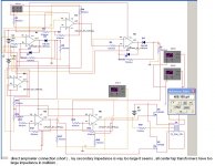
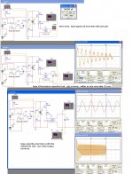
Anyways , these simulations are crap , there is no good transformer with center tap with this free-version multisim from a book , all secondaries are messed up , its as if this was meant for tubes , I dont know much about these transformers . I am aware of the forumula for a voltage drop across a component is = current squares * impedance .
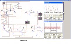
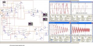
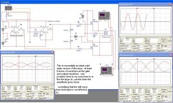
As you can see , my self-made circuit topology actually works , loves resonant loads and inductive loads , large capacitance not so good , still gives a tiny amplitude sine after a bit settling time , I guess the lower the secondary impedance the better it is for capacitive loads ? It seems to be quite similar to the single ended in terms of various reactive loads besides the tiny little distortion , to me that is very acceptable . I think I will go with my design after all and start designing a pcb , I like the simplicity of it , I like the adjustable biasing on both legs , I like the direct coupling and the simple power supply . If you notice the npn voltage follower this stage might not be used , its just to isolate capacitive loads and make the op amps job easier . Modern op amps are good enough I think , I dont believe these people that say many active components = bad , I am eyeing up a particular op amp , the tle2142 . -1 gain stable , very fast settling , very fast slew rate , high output swing , very low offset voltage , low noise . Cheap and available in 4 channel version so the voltage gain and rectifier can be on the same chip for best matching possible , good for +- 18 volt rail and compensated for capacitive loads .. My power supply will be a +-18 volt regulated supply with an oversized positive rail . Mosfets will run on battery power or a 15 volt power supply . Hope this is high enough to eliminate gate oscillation with the lateral mosfets .
Precision Amplifier - Wide Bandwidth - TLE2144A - TI.com
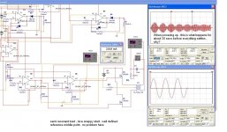
Here are some simulations , obervation , circuit waveforms . Might seem noobish but heh ... All these were taken at 20 khz ... Maybe somebody can answer these little question and observations I put there
Comments are very welcomed . Do not read this thread anymore if you are not gonna comment
Here are some observations/simulatins from my circuit design , I just wanna make an power amplifier that can handle reactive loads and stay sine , maybe with a little power with that , a capable sine wave oscillator if you will , for tesla experimets . So I am a bit going blind here since my load is a total mystery , I guess the transformer needs to be matched to the still undiscovered load , Or maybe I will go for a one size fits all impedance bridging transformer instead , is there such a thing as a low impedance transformer with Ok coupling factor ?
Anyways , these simulations are crap , there is no good transformer with center tap with this free-version multisim from a book , all secondaries are messed up , its as if this was meant for tubes , I dont know much about these transformers . I am aware of the forumula for a voltage drop across a component is = current squares * impedance .
As you can see , my self-made circuit topology actually works , loves resonant loads and inductive loads , large capacitance not so good , still gives a tiny amplitude sine after a bit settling time , I guess the lower the secondary impedance the better it is for capacitive loads ? It seems to be quite similar to the single ended in terms of various reactive loads besides the tiny little distortion , to me that is very acceptable . I think I will go with my design after all and start designing a pcb , I like the simplicity of it , I like the adjustable biasing on both legs , I like the direct coupling and the simple power supply . If you notice the npn voltage follower this stage might not be used , its just to isolate capacitive loads and make the op amps job easier . Modern op amps are good enough I think , I dont believe these people that say many active components = bad , I am eyeing up a particular op amp , the tle2142 . -1 gain stable , very fast settling , very fast slew rate , high output swing , very low offset voltage , low noise . Cheap and available in 4 channel version so the voltage gain and rectifier can be on the same chip for best matching possible , good for +- 18 volt rail and compensated for capacitive loads .. My power supply will be a +-18 volt regulated supply with an oversized positive rail . Mosfets will run on battery power or a 15 volt power supply . Hope this is high enough to eliminate gate oscillation with the lateral mosfets .
Precision Amplifier - Wide Bandwidth - TLE2144A - TI.com
Here are some simulations , obervation , circuit waveforms . Might seem noobish but heh ... All these were taken at 20 khz ... Maybe somebody can answer these little question and observations I put there
Comments are very welcomed . Do not read this thread anymore if you are not gonna comment
Attachments
Last edited:
82 people read this post and didnt reply , most of them have small wieners and bad haircuts . ( he who replies about this sentence and not about general electronics is as described in this sentence )
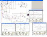
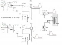
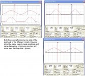
Here is my idea , I like this better than the zeus if the only disadvantage is the slight distortion , wich is more like an acceleration , not at all a crossover distortion . The idea is basicly a halfwave biased in continous conduction to avoid bemf issues and kinks , simple as that . If you know how to make a half wave biased with another technique plz do share .
Looking from the basic superposition of the waveforms of same peak amplitude and same bias current , my technique looks/is more efficient . Also , it does not suffer from bad efficiency at lower amplitude . As you can see from the very basic pictures .
So to the experts , lets start a debate about this with passionate opinions , I am wondering what is the difference between the 2 techniques , they both give the same output at the secondary , one has a slight distortion , one has bad efficiency . But wich one is the best @ being stable with all kinds of reactive loads . What is YOUR opinion ?
Attachments
Last edited:
Build it, looks like you've simmed it to the point that you need to see what it does in real time.
Thx you for the comment , you have given me confidence .
Yes I am making this on a pcb , my design and a zeus like to see wich comes out on top .
I have a bunch of crazy oscillators I made I wanna try out with power , learning amplifier basics was harder than expected yet I have much experience @ imaginating circuits only not the right knowledge for applying the math to actually finish the things I make , I actually invented a massive 3 channel harmonics phase shift pure oscillator that is 100% stable . Using the appropriate analog logic that I invented with a ramp wave and comparators I created this I can make a 0-2 Khz phase shift pure sine oscillator that has no jitter and phasing issues that I can adjust with a single pot phase or amplitude . I have also built a self-made 3 wave mixer , a self-made 3 phase driver using only cmos .
Last edited:
Your schemetics are almost impossible to read. If I could read them, I might comment; just thought you might like to know this.
the schematic is called untitled43 , in my sim I have omitted a few things from that design for simplicity reasons , there is no npn voltage follower as well . All the chaotic sim schematics with diodes in em are the design mentionned with different loads .
The other schematics are very simple , there is nothing to see there .
The other schematics are very simple , there is nothing to see there .
Last edited:
- Status
- Not open for further replies.
- Home
- Amplifiers
- Solid State
- This is functionnal