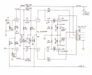
A Different Kind Of Triode Audio Amplifier
Part One of this project was published in the Volume 11, Number 2 Issue of Glass Audio magazine in May 1999. It describes a simple method of providing the very large grid drive voltage required by low mu vacuum power tubes such as the 6080/6AS7G family. The circuit appears to be fairly obvious but it seems no one has previously published anything like it.
Part Two appeared a month later in Volume 11, Number 3 Issue of Glass Audio magazine. Circuit modifications are suggested so that other power triodes such as the 2A3 & 300B could utilize the basic circuit. A circuit simplification which avoids the use of the Ultra Linear Output Transformer in the first article is covered.
The circuit also appeared in short form in the July 1998 issue of Electronics World.
Attachments

Last edited by a moderator:
Look at old McIntosh amps from the early 60's ... Similar stuff..
Boot-strapped driver from the plate winding, which allows the gain of the driver to approach it's own mu value...
Boot-strapped driver from the plate winding, which allows the gain of the driver to approach it's own mu value...
I agree with Cerrem. Bootstrapped driver is nothing new and it has always been a feature of McIntosh amps. Crowhurst wrote many articles in the 50-60ies about this kind of bootstrapping.
Part Two appeared a month later in Volume 11, Number 3 Issue of Glass Audio magazine. Circuit modifications are suggested so that other power triodes such as the 2A3 & 300B could utilize the basic circuit. A circuit simplification which avoids the use of the Ultra Linear Output Transformer in the first article is covered.
One of the advantages of tubes like 2A3 and 300B is the lower Zout. If you bootstrap the driver the Zout will be worse. There is alwys a price to pay.
And Electrovoice used boot strapping of the driver as well. But in this example boot strapping is used to drive low mu triodes, something no one else did as far as I know. If anyone is aware of that, pls let me know with a reference to the circuit.
The 6AS7/6080 family has significantly lower plate resistance then either the 2A3 or 300B, at a fraction of the cost.
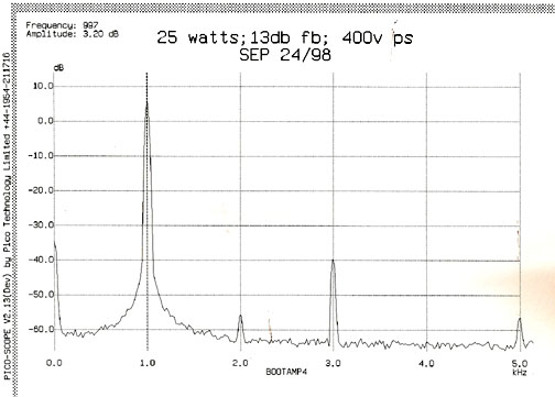
The +ve FB resulting from the boot strapping is only 1.5 to 2db, I have measured it. This is an application where the advantages exceed the disadvantages.
The 6AS7/6080 family has significantly lower plate resistance then either the 2A3 or 300B, at a fraction of the cost.
The +ve FB resulting from the boot strapping is only 1.5 to 2db, I have measured it. This is an application where the advantages exceed the disadvantages.
No one has done it with low mu triodes because it is not needed or economy is not a priority, especially with 300B and 2A3. At least I have never seen it. A DHT is too "noble" device to use such a "vulgar" solution.🙂
The 6080 is popular in OTL amps. Except Audio Tekne I do not remember another commercial amp that uses such tube with output transformer. Probably because of its short life.
Of course, because of the low mu, everything happens on smaller scale. It doesn't give the same advantages as with pentodes. In a circuit like the McIntosh, where the gain of the output tube is reduced by a factor of 3-8 times because of the local feedback, using the bootstrap allows to keep things normal (i.e. no need for expensive drivers or additional PSU) and the Zout is still equal or better than a non-bootstrapped 300B amp. Loop fb usually makes it very low again.
The bad effects of the positive feedback from bootstrapping can be avoided by putting a CCS in place of the load resistor (ie, top of the CCS still bootstrapped to provide the high variable B+). With the correct amount of bootstrap V swing, the CCS Vac compliance only needs to handle the distortion component then (providing isolation).
The CCS load provides optimum gain for the driver then, and blocks any re-entrant distortion from the positive feedback. (mentioned this idea eons ago for fixing the Macs, but it got the usual in one ear and out the other response)
The CCS load provides optimum gain for the driver then, and blocks any re-entrant distortion from the positive feedback. (mentioned this idea eons ago for fixing the Macs, but it got the usual in one ear and out the other response)
The bad effects of the positive feedback from bootstrapping can be avoided by putting a CCS in place of the load resistor (ie, top of the CCS still bootstrapped to provide the high variable B+). With the correct amount of bootstrap V swing, the CCS Vac compliance only needs to handle the distortion component then (providing isolation).
The CCS load provides optimum gain for the driver then, and blocks any re-entrant distortion from the positive feedback. (mentioned this idea eons ago for fixing the Macs, but it got the usual in one ear and out the other response)
I felt pretty stupid when someone pointed this out to me after I had already done things the hard way and built an 800V supply just for the driver. There was a free supply sitting there all along and I just didn't see it.
I also like to use some form of positive feedback. Bootstrapping the anode load of any tube will increase the output voltage while reducing the distortion. See my thread "http://www.diyaudio.com/forums/tubes-valves/224046-neutralizing-amplifier.html" here, some years ago.
Last edited:
Positive feedback can be used to make some interesting phase splitters too.
Just use the inverted output to generate the missing input signal phase. Keep the loop gain just a "skosh" below unity, so you don't get an oscillator. Could be used with a CCS tailed differential stage or a beam deflection tube to provide the missing differential input. If you put BOTH positive feedback paths in place, then the signal input node becomes high Z also. (typically already is though) (again, watch the loop gains carefully...)
Just use the inverted output to generate the missing input signal phase. Keep the loop gain just a "skosh" below unity, so you don't get an oscillator. Could be used with a CCS tailed differential stage or a beam deflection tube to provide the missing differential input. If you put BOTH positive feedback paths in place, then the signal input node becomes high Z also. (typically already is though) (again, watch the loop gains carefully...)
Last edited:
A Different Kind Of Triode Audio Amplifier World.
With 2nd harmonic diminished so much, why even bother with triode amp? 🙁
No, no and no. If you do that, the entire amplifier will become narrow and narrow in BW, and when the closed loop is 1, then it oscillates at only 1 main frequency, demonstrating that the BW has shrank to few hz.
"No, no and no. ..."
The amplifier open loop bandwidth does, simply because the open loop gain goes to (near) infinity in that vicinity. Once you put the usual global N Fdbk loop around it, all is restored to normal.
Using just the one local positive feedback to the missing phase splitter input does not cause any additional V gain for the stage, as long as it is below unity. Some added critical damping (dominant pole RC to ground at FB driven splitter input) should minimize settling time. (ie, keep the gain/phase margin of the local loop under control)
Last edited:
Yes, local positive Fdbk in the splitter, global N Fdbk for the amplifier.
I haven't tried this yet. Could be some issues.
Even for the open (no global N Fdbk) loop case, using a dominant pole below the natural oscillation freq. (the RC to ground on the P Fdbk driven splitter input) should allow one to keep the bandwidth wide enough for audio, as long as the pole is above the maximum audio band. Otherwise, the phase splitter starts to lose half its gain there, from lack of the 2nd differential input above that freq.
So one would just set the RC cutoff somewhere loosely above the audio band and hope for the best.
(no appreciable positive feedback remaining up at the phase splitter stage natural oscillation freq.)
Last edited:
In the Wallman and Valley's book "Vacuum Tube Amplifiers", there are several examples of circuits using both positive and negative feedback. I tryed some of them.
Going back to the original Op's post about positive feedbacks from UL taps:
That started me thinking. (clever and devious seem to be synonyms in the dictionary)
Just suppose (entering the Twilight Zone now, caution!).....
One of the fun ways of analyzing various feedback schemes is to assume they work well, then derive the needed inputs from the (assumed working) outputs.
Take the recent "Crazy Drive" pentode drive scheme, where grid2 is V driven, and grid1 gets an R derived current drive from that. Tube output current is near proportional to the driven screen voltage.
Now suppose we take a P-P pentode output stage with a UL tapped OT, and we derive the needed g2 screen drives from the cross coupled UL taps. (a positive fdbk version of the usual UL scheme) Then we supply the R derived g1 current drives from a diff. pentode driver stage (CCS loaded, so current drives).
Would it still give linear "Crazy Drive" results? And now only using low voltage current drives. It does sound dangerous. Maybe it could work. Maybe not. (some RC HF gain killers on the screens for sure)
Time to get some cheap tubes out.
--
Last edited:
One of the fun ways of analyzing various feedback schemes is to assume they work well, then derive the needed inputs from the (assumed working) outputs.
Take the recent "Crazy Drive" pentode drive scheme, where grid2 is V driven, and grid1 gets an R derived current drive from that. Output current is near proportional to driven screen voltage.
Now suppose we take a P-P pentode output stage with a UL tapped OT, and we derive the needed g2 screen drives from the cross coupled UL taps. (a positive fdbk version of the usual UL scheme) Then we supply the R derived g1 current drives from a diff. pentode driver stage (CCS loaded, so current drives).
Would it still give linear "Crazy Drive" results? And now only using low voltage current drives. It does sound dangerous. Maybe it could work. Maybe not.
Time to get some cheap tubes out.
--
Smokingamp, Menno Vanderveen has invented a similar topo that he produces. He calls it superpentode. He cross couples the UL feedbacks to give positive feedback, but he only uses it in conjunction with his OT that includes 10% cathode feedback (NOT the unbypassed resistor in cathode of finals type) This seems to be a feature of most regenerative circuits that you do not want to oscillate. You have to include some kind of negative feedback in addition to make it stable.
In the superpentode case he claims the biggest advantage isn't the additional power over straight pentode, which is marginal at best, but the superior damping factor that overcomes the loose uncontrolled bass in many pentode output designs. I haven't actually constructed the one but am planning to since I have the Plitron OT that has 10% neg fb.
One additional point. My own preference would be to keep both the regenerative and degenerative feedbacks within one stage. It just seems like a good idea on general principles. You then have a much clearer control frame in which to adjust parameters to get the results you would like. It just seems like otherwise it might be an uncontrollable experiment where unanticipated real world stray resonances might destroy carefully worked out controlled lab results.
Yes, generally one wants the N Fdbk to dominate the P Fdbk. And keep the P Fdbk below unity loop gain too.
In Menno's superpentode scheme, the UL taps at say 40% would have to work with a tube with greater than 4.0 internal Mu between g2 and g1, so that the P Fdbk gets reduced to below the 10% CFB (the N Fdbk).
And if the UL taps were just 10%, like the CFB, it would be operating in normal pentode mode (constant V between g2 and cathode)
The phase accuracy at the UL taps, versus the plate taps, is an important issue too. Although much less so if the UL taps are already being used for positive Fdbk.
Last edited:
- Status
- Not open for further replies.
- Home
- Amplifiers
- Tubes / Valves
- Thinking Outside the Box - A Different Kind of Triode Audio Amplifier